Lithographic processing method, and device manufactured thereby

a technology of lithographic processing and processing method, applied in the field of lithographic apparatus, can solve the problems of small depth of focus and insensitivity to residual errors in exposure dose of irradiated target portions

Active Publication Date: 2012-05-22
ASML NETHERLANDS BV
View PDF2 Cites 6 Cited by
  • Summary
  • Abstract
  • Description
  • Claims
  • Application Information

AI Technical Summary

Benefits of technology

[0013]One aspect of embodiments of the present invention provides a method of splitting a lithographic pattern into a plurality of sub-patterns, including generating at least one test structure corresponding to one or more structures of interest in the lithographic pattern, varying the at least one test structure through a selected range of dimensions to produce a plurality of varied test structures, determining a plurality of values for an image quality metric for images of the plurality of varied test structures, analyzing the values to determine ranges of dimensions for which a pattern split would improve the image quality metric, and generating a plurality of sub-patterns of the lithographic pattern in accordance with the determined ranges.

Problems solved by technology

These measures have as side effect that depth of focus and insensitivity to residual errors in exposure dose of irradiated target portions become small.

Method used


Image

  • Lithographic processing method, and device manufactured thereby
  • Lithographic processing method, and device manufactured thereby
  • Lithographic processing method, and device manufactured thereby

Examples


Embodiment Construction

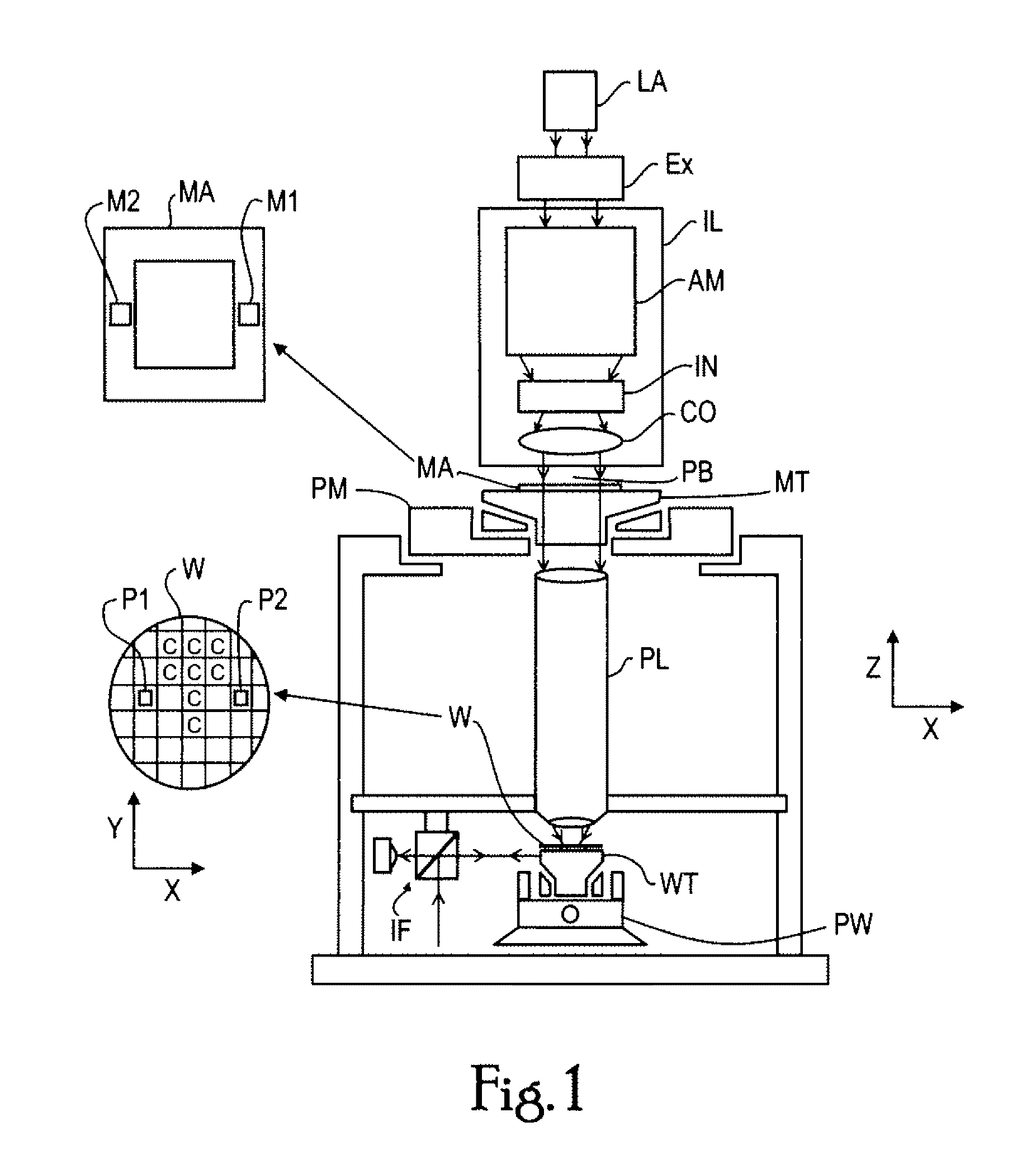
[0045]FIG. 1 schematically depicts a lithographic projection apparatus which may be used in the methods of the invention. The apparatus comprises:[0046]a radiation system Ex, IL, for supplying a projection beam PB of radiation (e.g., UV radiation or DUV radiation of a wavelength of less than about 270 nm, such as wavelengths of 248, 193, 157, and 126 nm radiation). In this particular case, the radiation system also comprises a radiation source LA;[0047]a first object table (mask table) MT provided with a mask holder for holding a mask MA (e.g., a reticle);[0048]a second object table (substrate table) WT provided with a substrate holder for holding a substrate W (e.g., a resist-coated silicon wafer); and[0049]a projection system (“lens”) PL (e.g., a quartz and / or CaF2 lens system or a catadioptric system comprising lens elements made from such materials, either suitable for conventional imaging or suitable for imaging in the presence of an immersion fluid) for imaging an irradiated p...


PUM

PropertyMeasurementUnit
widthsaaaaaaaaaa
wavelengthaaaaaaaaaa

Abstract

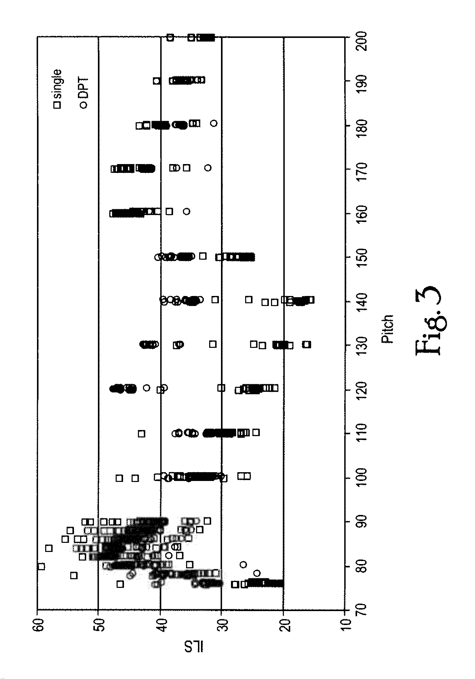
A method of splitting a lithographic pattern into two sub-patterns, includes generating test structures corresponding to structures of interest in the lithographic pattern, varying the test structures through a selected range of dimensions, simulating an image of the test structures, determining an image quality metric for the simulated image, analyzing the determined image quality metric to determine pitch ranges for which split improves the image quality metric and ranges for which split does not improve the image quality metric, and generating the two sub-patterns in accordance with the determined pitch ranges.

Description

CROSS-REFERENCE TO RELATED APPLICATIONS[0001]This application claims the benefit of priority from U.S. Provisional Patent Application Ser. No. 61 / 100,544, filed on Sep. 26, 2008, the contents of which is incorporated herein by reference in its entirety.FIELD OF THE INVENTION[0002]The present invention relates generally to a lithographic apparatus and more particularly to a method of exposure using multiple exposures.DESCRIPTION OF THE RELATED ART[0003]A lithographic apparatus is a machine that applies a desired pattern onto a target portion of a substrate. The apparatus generally comprises a radiation system for supplying a beam of radiation, a support structure for supporting a patterning device, the patterning device serving to pattern the beam, a substrate table for holding a substrate, and a projection system for projecting the patterned beam of radiation onto a target portion of the substrate. Lithographic apparatus can be used, for example, in the manufacture of integrated cir...

Claims


Application Information

Patent Timeline
Patent Type & Authority Patents(United States)
IPC IPC(8): G03F9/00
CPCG03F1/144G03F1/36G03F7/70441G03F7/70466G03F1/70
Inventor HSU, DUAN-FU STEPHENKIM, JOOBYOUNG
Owner ASML NETHERLANDS BV
Why Eureka
Try Eureka