
Combi-card and method for making the same

a technology of combi-cards and cards, applied in the field of combi-cards and a method of making the same, can solve the problems of reducing durability, affecting the use of the same, and causing contact failure, etc., and achieves excellent adhesive strength, excellent adhesive strength, and good electrical conductivity.

Inactive Publication Date: 2012-05-22
KOREA MINTING SECURITY PRINTING & ID CARD OPERATING CORP
View PDF18 Cites 13 Cited by
  • Summary
  • Abstract
  • Description
  • Claims
  • Application Information

AI Technical Summary

Benefits of technology

The present invention provides a new method for making a combinational IC card (combi-card) that overcomes the problems of conventional methods. This new method makes the card more reliable, durable, and cost-effective. The patent also includes a method for attaching the COB (chip on board) to the card body.

Problems solved by technology

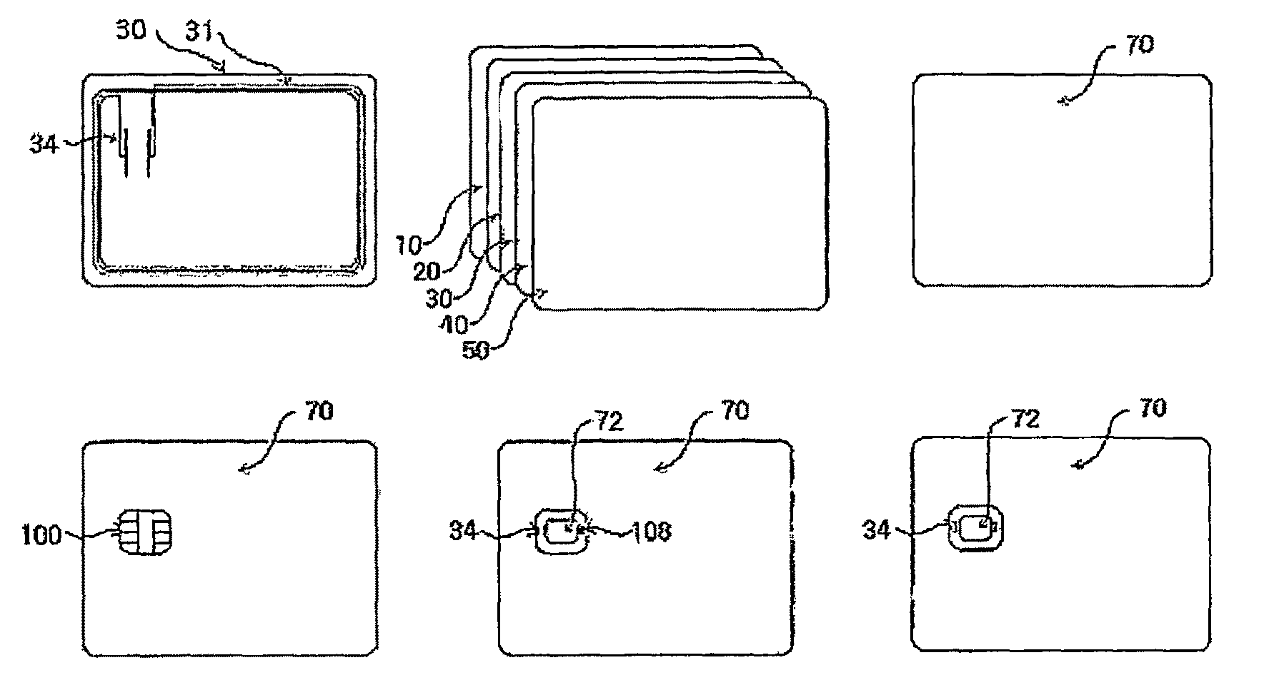
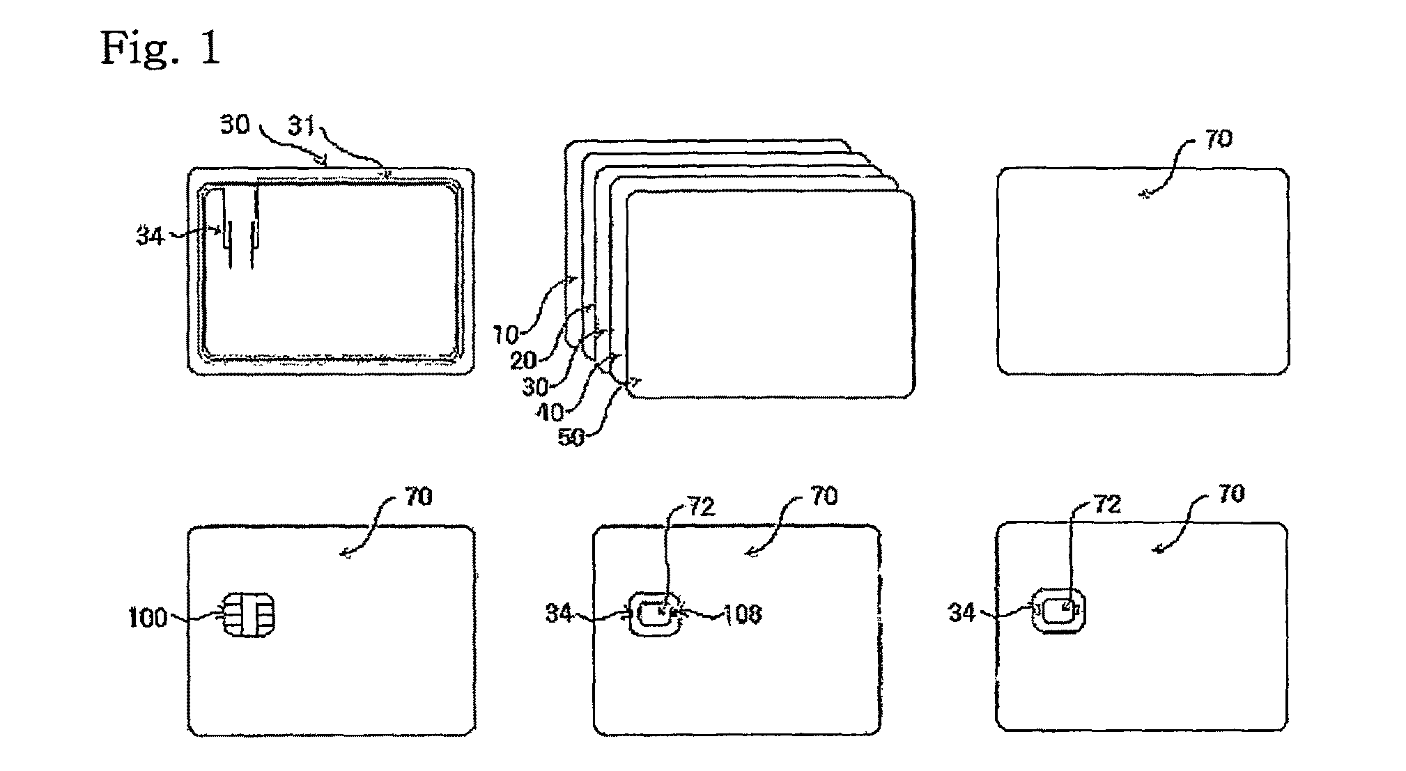
However, in the above conventional method, there arises a problem in that, if the bending or torsional force is applied to the combi-card, a crack occurs in the interface of the conductive adhesive 108 and so the contact failure is arisen between the contacts 104 of the COB and the antenna terminal 34 of the card body 70.
This is the structural problem arisen from a conventional combi-card manufacturing process.
Since the adhesive strength of the Hot-Melt tape 111 or the thermosetting adhesive connecting the two layers is insufficient, and the combi-card deteriorates in its function by aging and fatigue of the conductive adhesive 108, a lot of defective products are created.
In addition, since the IC chip module is not adhered by an adhesive, the durability becomes decreased and the manufacturing costs increase.

Method used


Image

  • Combi-card and method for making the same
  • Combi-card and method for making the same
  • Combi-card and method for making the same

Examples


embodiment 1

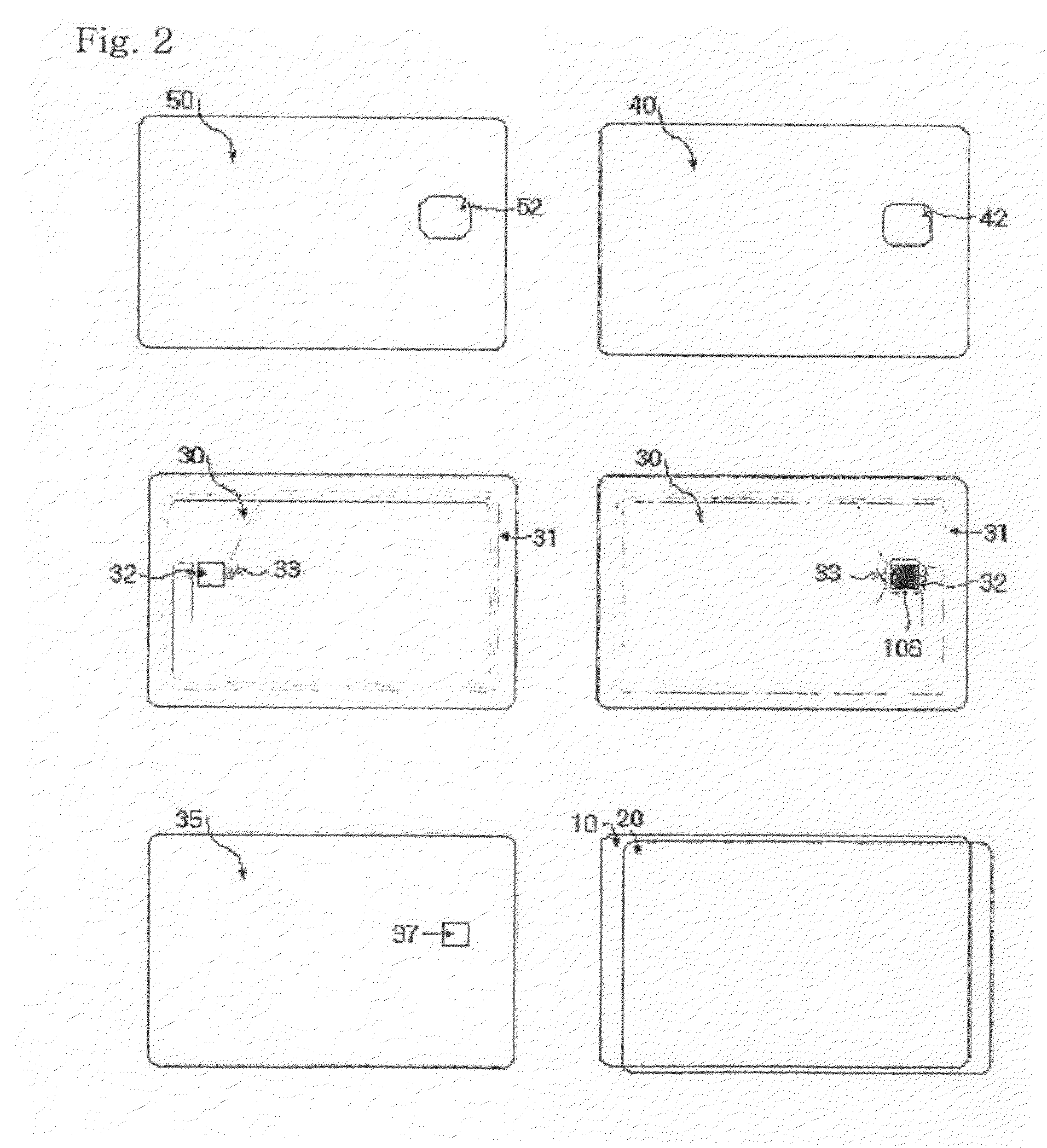
[0077]For a correct positioning of the COB 100 and the antenna coil insertion layer 30, as in FIG. 9, the respective two round-tipped pin bars 210 (each diameter is 5 mm or less and height is 5 mm or less) are set up on the top and bottom surfaces of the metal die 200, and the COB-shaped pit 220 is formed on a surface of the die 200, at a depth of 160-230 μm. The COB 100 is inserted into the pit 220, so that the ACF 112 pre-treated on the COB 100 can face up. Then, the dam positioning opening 32 of the antenna coil insertion layer 30, which is 100-250 μm thick and on which the conductive fiber antenna terminal 33 is formed, is aligned by using the pin bars 210, and thereafter, by applying heat and pressure, the COB 100 is provisionally adhered to the antenna coil insertion layer 30. By doing so, the sheet for antenna coil insertion, in which the ACF-applied COB contact 104 is adhered and electrically connected to the conductive fiber antenna terminal 33 directly, is formed as is sho...

embodiment 2

[0080]As shown in FIG. 3, the lower protection layer 10, which is 50-100 μm thick; the lower printing layer 20, which is 100-200 μm thick; the antenna coil thickness-adjusting layer 35, which is 100-250 μm thick and on which the COB dam positioning opening 37 is formed; the antenna coil insertion layer 30, which is 100-200 μm thick and on which the COB dam positioning opening 32 and the conductive fiber antenna terminal 33 are formed; the upper printing layer 40 which is 100-200 μm thick and on which the COB positioning opening 42 is formed; and the upper protection layer 50 which is 50-100 μm thick and on which the COB positioning opening 52 is formed, are in turn stacked upward. After the air and the static electricity between the respective layers has been removed by a roller, the COB 100, on which the ACF 112 is pre-treated, is inserted into the opening 72 to which the COB 100 will be secured. Then, by applying heat and pressure, the ACF-applied COB contact 104 is adhered and el...


PUM

PropertyMeasurementUnit
temperatureaaaaaaaaaa
diameteraaaaaaaaaa
diameteraaaaaaaaaa

Abstract

The present invention relates to a combi-card which can be used in a contact-type or noncontact-type fashion and a method for manufacturing the same. More particularly, this invention relates to a combi-card and a method for making the same, in which an inlay layer on which an antenna terminal made of a coil or conductive fiber is formed and a COB (chip on board) on which ACF (anisotropic conductor film) is applied, are pre-treated by a heating head and the like, the COB is attached to an antenna coil insertion layer, and an upper printing sheet with a protection film, and a lower printing sheet with a protection film, which are cut out to be suitable for the COB shape, are stacked to construct a combi-card.

Description

[0001]This application is a US national stage of International Application No. PCT / KR2005 / 001828, filed 15 Jun. 2005, published on 29 Dec. 2005 with number WO 2005 / 124672 A1, said international patent application claiming the benefit of Korean Utility Model Patent Application No. 10-2004-0044655, filed 16 Jun. 2004, each hereby incorporated by reference herein.TECHNICAL FIELD[0002]The present invention relates to a combinational card (hereinafter, referred to as “combi-card”) which can be used in a contact-type or noncontact-type fashion and a method for manufacturing the same. More particularly, this invention relates to a combi-card and a method for making the same, in which an inlay layer on which an antenna terminal made of a coil or conductive fiber is formed and a COB (chip on board) on which ACF (anisotropic conductor film) is applied, are pre-treated by a heating head and the like, the COB is attached to an antenna coil insertion layer, and an upper printing sheet with a pro...

Claims


Application Information

Patent Timeline
Patent Type & Authority Patents(United States)
IPC IPC(8): G06K19/06G06K19/077
CPCG06K19/077G06K19/07769G06K19/0775Y10T29/49018
Inventor KWON, SANG-CHELRYU, JIN-HOCHAE, JONG-HOONHONG, JIN-KI
Owner KOREA MINTING SECURITY PRINTING & ID CARD OPERATING CORP
Learn More