Systems and methods for visible light source evaluation

a visible light source and evaluation system technology, applied in the field of semiconductor laser evaluation, can solve the problems of reducing affecting the optical output power, and affecting the accuracy of the visible light source, so as to minimize wavelength thermal drift and cavity mode-hopping, reduce the overall cost of the fabrication process, and reduce the effect of overall cos

Inactive Publication Date: 2012-05-15
CORNING INC
View PDF16 Cites 2 Cited by
  • Summary
  • Abstract
  • Description
  • Claims
  • Application Information

AI Technical Summary

Problems solved by technology

However, wavelength thermal drift and cavity mode-hopping in semiconductor lasers may adversely affect optical output power and create noticeable defects in the scanned laser image produced by laser scanner system (particularly those emitting wavelength-converted optical radiation in the green spectral range).
However, the complicated electronics necessary to produce such high frequency gain currents are not cost effective or easily implemented into testing procedures of high-volume production environments.
For example, high-frequency, high-gain current gain drive signals may require that the test equipment be located very close to the laser under test and may also produce significant electrical noise.
Further, the high-frequency, high-gain current gain drive signals may necessitate soldered connections of the laser under test to the evaluation equipment, which may be unacceptable in a high-volume production environment.
However, testing each visible light source / semiconductor laser with such high-frequency and high gain current presents significant problems in fully-automated, high-volume manufacturing environments.
For example, test methods utilizing high-frequency, high-current drive signals require expensive circuitry, prevents the drive signal from being located in relatively close proximity to the light source under test, and produce undesirable electrical noise.

Method used


Image

  • Systems and methods for visible light source evaluation
  • Systems and methods for visible light source evaluation
  • Systems and methods for visible light source evaluation

Examples


Embodiment Construction

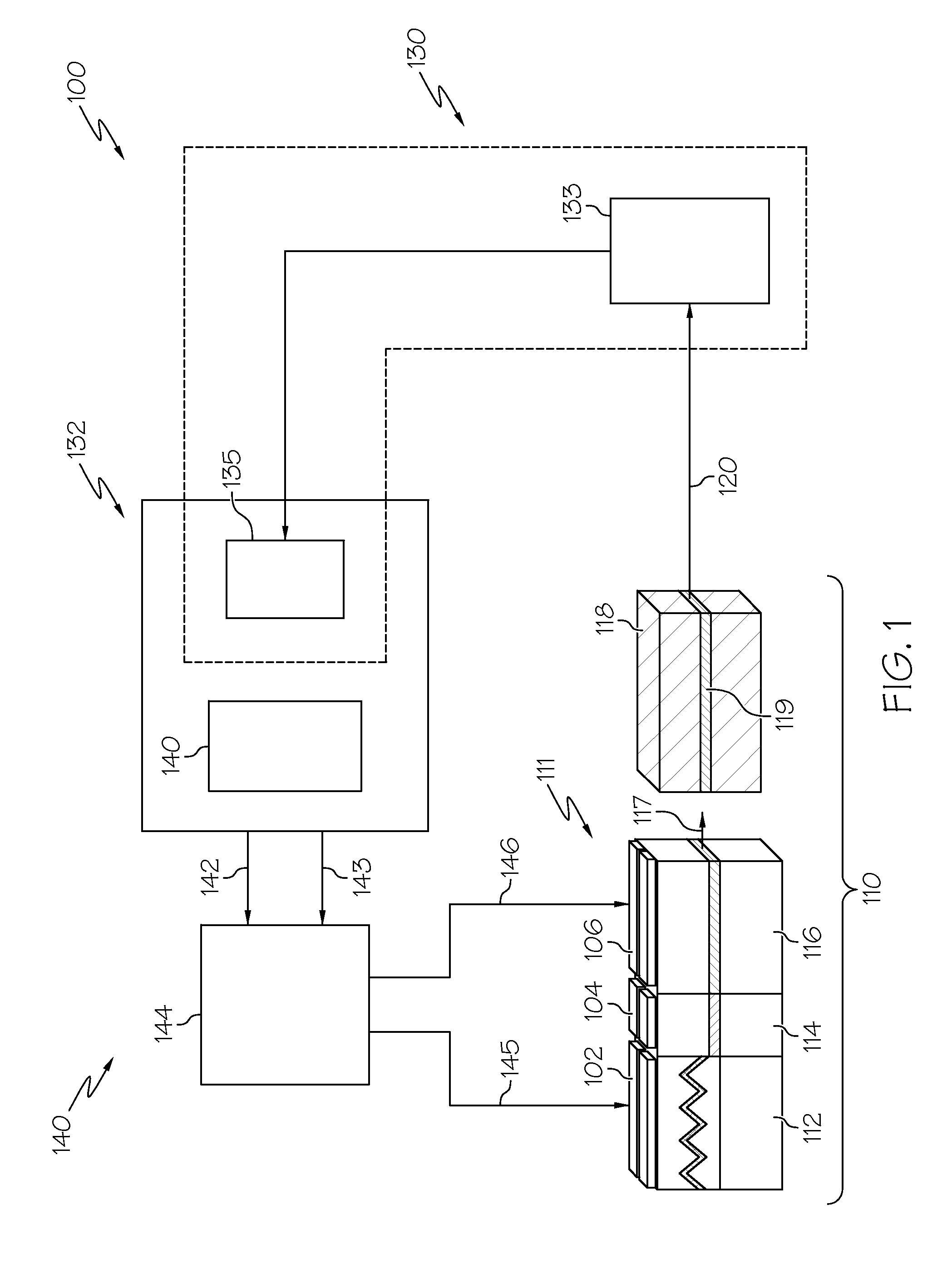
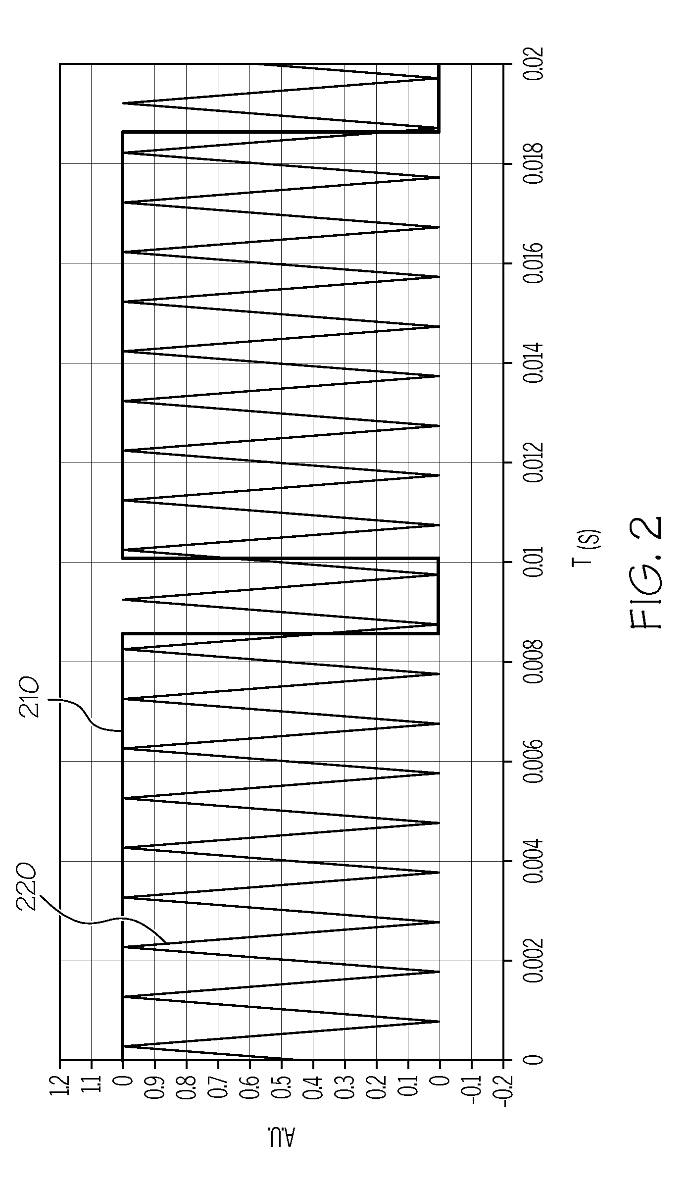
[0018]Embodiments described herein are directed to systems and methods for evaluating visible light sources and associated semiconductor lasers and wavelength conversion devices using a low frequency periodic gain drive signal applied to the gain section and a triangular wave drive signal to a wavelength selective section of the semiconductor laser. The semiconductor laser emits a plurality of optical output pulses in response to the periodic gain drive signal and the triangular wave drive signal that are converted into higher harmonics by a wavelength conversion device. These pulses are detected and analyzed to determine if the visible light source satisfies particular specification requirements.

[0019]A system 100 for evaluating a visible light source 110 under test is illustrated in FIG. 1. The system 100 generally comprises a drive electronics controller 140 and an optical power detection and analysis module 130. As described in more detail below, components of the drive electron...


PUM


Abstract

Particular embodiments of the present disclosure relate systems and methods for evaluating visible light sources. According to one embodiment, a method of evaluating a visible light source including a semiconductor laser having a gain section, a wavelength selective section, and a phase section includes applying a gain drive signal to the gain section of the semiconductor laser at a gain modulation frequency, and applying a triangular wave drive signal to the wavelength selective section of the semiconductor laser at a wavelength selective modulation frequency that is greater than the gain modulation frequency. The light source emits a plurality of optical output pulses. Output power values of the optical output pulses at a selected wavelength are detected. The output power value of one or more selected output pulses is compared with an output power threshold value to generate an indication of whether the visible light source satisfies an output power specification.

Description

BACKGROUND[0001]1. Field[0002]Embodiments of the present disclosure generally relate to the evaluation of semiconductor lasers. More specifically, the embodiments relate to systems and methods of evaluating the optical output of visible light sources comprising a wavelength conversion device and a semiconductor laser having a gain section, a wavelength selective section, and a phase section.[0003]2. Technical Background[0004]Semiconductor lasers, such as distributed Bragg reflector (DBR) lasers, are being utilized in an increasing number of applications. For example, semiconductor lasers capable of producing optical radiation in the red, blue and green optical spectrums may be incorporated into a laser projector to produce scanned laser images. However, wavelength thermal drift and cavity mode-hopping in semiconductor lasers may adversely affect optical output power and create noticeable defects in the scanned laser image produced by laser scanner system (particularly those emitting...

Claims


Application Information

Patent Timeline
Patent Type & Authority Patents(United States)
IPC IPC(8): H01S3/10G01C3/08G01J1/42
CPCH01S5/0014H01S5/0092H01S5/06251H01S5/06256
Inventor GREGORSKI, STEVEN JOSEPH
Owner CORNING INC
Why Eureka
Try Eureka