
Turn-back flow EDI

a technology of electrodeionization apparatus and flow, which is applied in the direction of electrodialysis, refrigeration machines, refrigeration components, etc., can solve the problems of irreversible damage to the membranes of the electrodeionization apparatus, poor pressure endurance, and high energy consumption, and achieves easy scaling and inability to maintain product quality

Active Publication Date: 2012-05-08
ZHEJIANG OMEX ENVIRONMENTAL ENG CO LTD
View PDF34 Cites 4 Cited by
  • Summary
  • Abstract
  • Description
  • Claims
  • Application Information

AI Technical Summary

Benefits of technology

This design achieves stable and high-level deionization of water, effectively removes weak electrolytes, reduces electric power consumption, and lowers manufacturing costs by optimizing the use of materials and simplifying maintenance.

Problems solved by technology

However, the structure has disadvantages of poor pressure endurance, ease to leak during operation, high maintenance (the filled resins can't be replaced), easily producing leakage of electric field due to its open electric field which results in high energy consumption.
In the prior art, the existence of organics in pretreated water often causes irreversible damages to the membranes of the electrodeionization apparatus, especially to filled ion exchange resins.
When being adsorbed by the resins (usually anion resins), the organics in the water will attach to the surfaces of the resin particulates and their network cracks, causing difficulties for the diffusion of ions.
This kind of adsorption is very stable and difficult to desorb, especially in the case that the organics enter the resin particulate structure and reach the interior exchange positions, where the organics will twist each other and can hardly be separated from the resin structure with any commonly used regeneration methods.
As a result, the overall exchange capacity of resin is decreased.
As a result, once the ion exchange passage is contaminated by the organics, the impact on the overall performance of the electrodeionization apparatus is much more severe than that on a common deionization (DI) unit.
Since the contaminated resins are difficult to be regenerated, if the structure of EDI makes it impractical to replace the resins, the entire EDI unit will be discarded.
In practice, particularly in the case of treating surface water, shallow groundwater or polluted groundwater, although the feed water will be generally pretreated with a conventional reverse osmosis process and the TOC of the product water will be controlled to a level below 0.5 ppm, the EDI apparatus breakdown frequently due to the accumulation of pollutants on the filled resins over long time of operation.
However, this leads to high energy consumption and high investment cost.
However, this helical wound structure has a defect of uneven distribution of current density.
However, in order to ensure the water yield of the apparatus, this structure has to be lengthened in axial direction, hence increasing the length of electrode.
Furthermore, the resistance of water flow increases due to the spiral flow of the dilute water, and the structure is complex, making it difficult to fill and replace the resins.
However, the design of the flow passage of the concentrate and the dilute is undesirable, making the pressure of the concentrated water higher than that of the dilute in certain areas, which results in the reverse permeation of the concentrate into the dilute chamber, adversely affecting the quality of the product water.

Method used


Image

  • Turn-back flow EDI
  • Turn-back flow EDI
  • Turn-back flow EDI

Examples


example 1

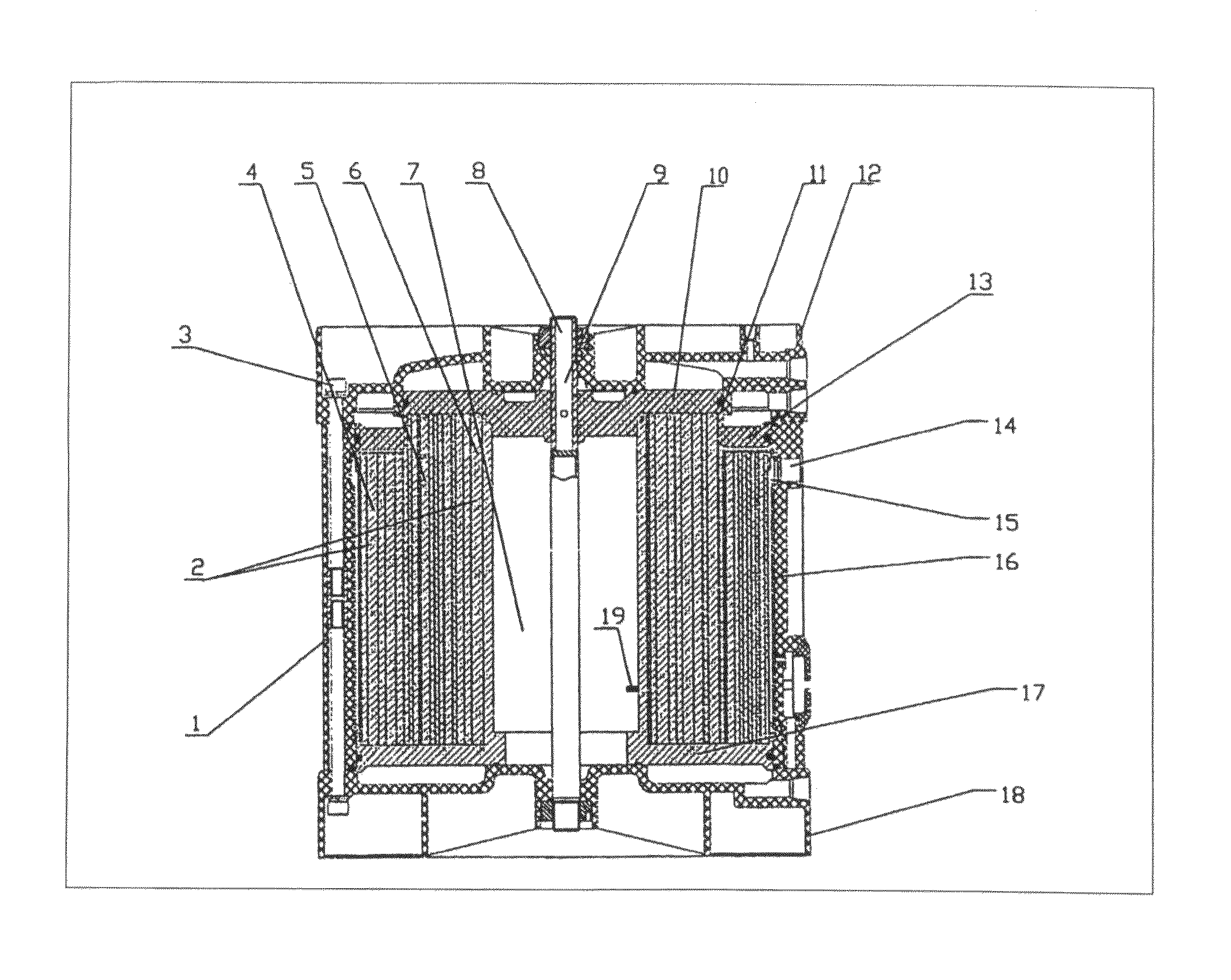
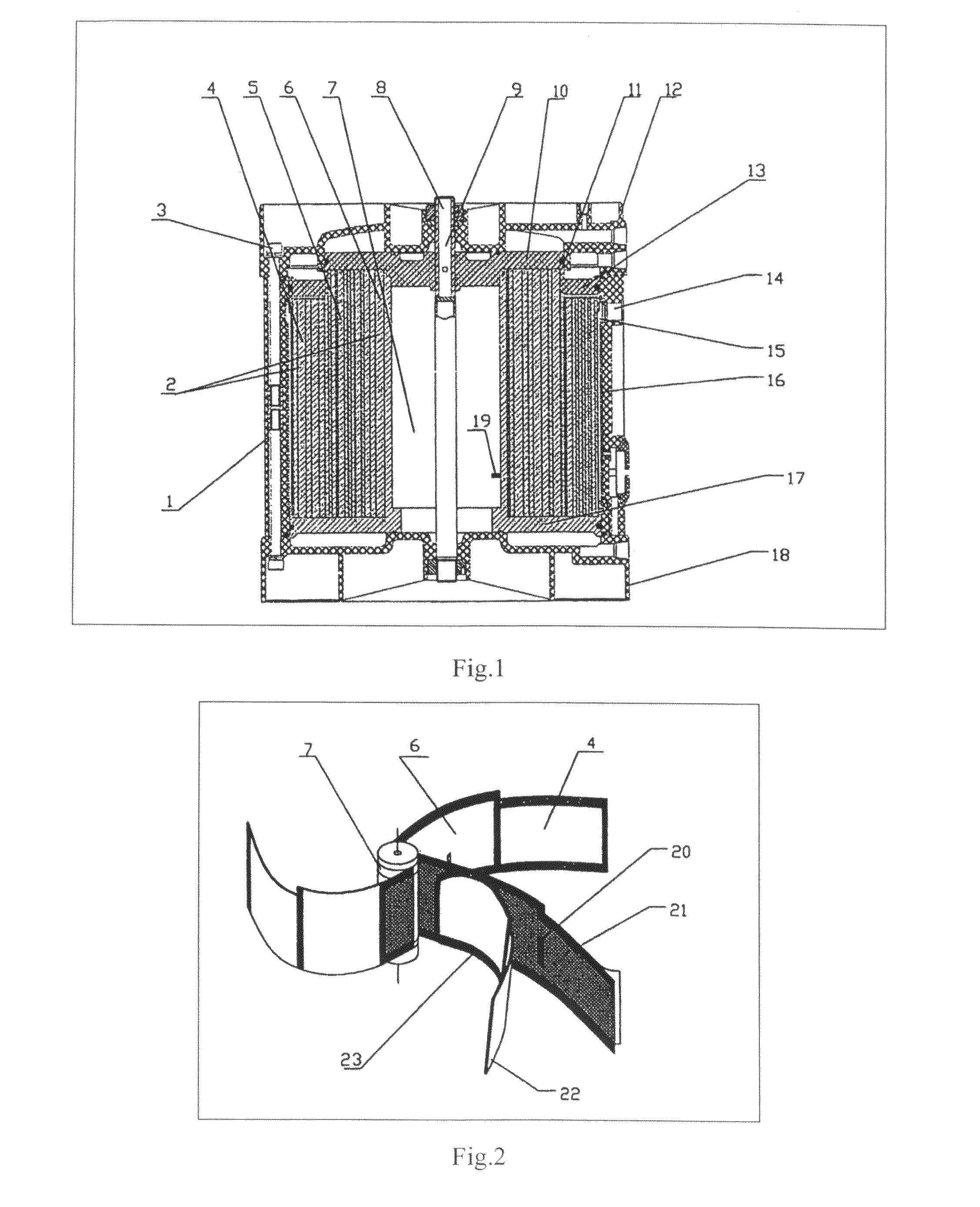
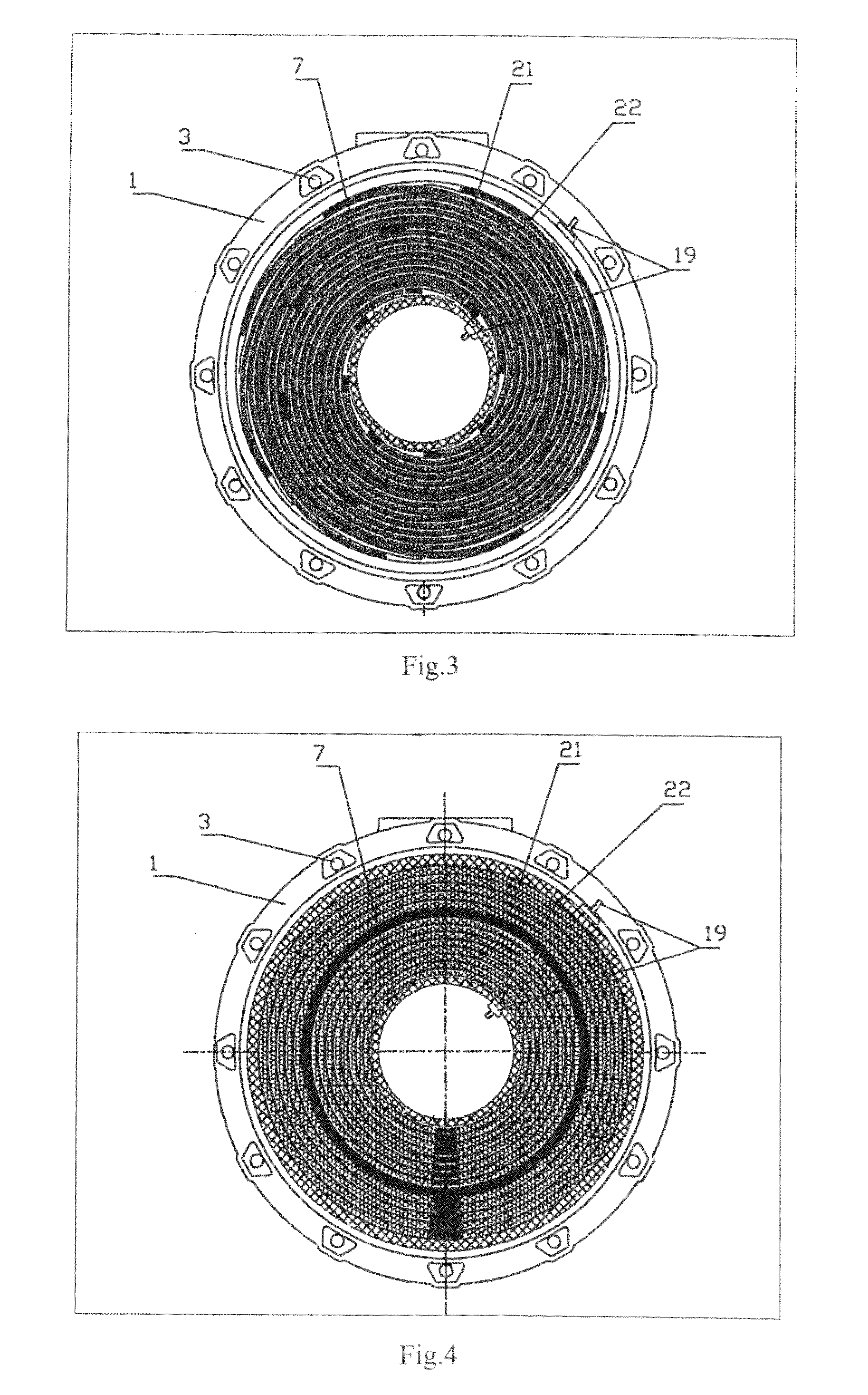
[0061]As shown in FIGS. 1, 2 and 3, a turn-back EDI apparatus has central pipe 7 as central axis. The central pipe 7 is made of engineering plastics pipe and covered with ruthenium-coated titanium sheet, which is extended from the electrode terminal 19 to act as the anode of the apparatus. Eight pairs of cation exchange membrane and anion exchange membrane 22 are distributed evenly in the circumferential direction of the central pipe 7. In other words, the circumference of the central pipe 7 is divided into eight parts equally with each part connecting with one end of cation exchange membrane and anion exchange membrane pair 22. Of the two ends of the cation exchange membrane and anion exchange membrane pair 22 perpendicular to the central pipe 7, one is flat, and the other is a ladder shape with a sealing element 11 disposed on the ladder. The sealing element is an end ring used for sealing the apparatus. The dilute chamber and the concentrate chamber 5 are disposed alternatively o...

example 2

[0066]As shown in FIGS. 1, 2 and 4, fifteen pairs of cation exchange membrane and anion exchange membrane 22 wind around the periphery of the central pipe of the turn-back EDI apparatus. The two ends of each pair of the cation exchange membrane and the anion exchange membrane 22 perpendicular to the central pipe 7 are adhered by epoxy resin. The net-separating partition 21 is disposed within the adhered cation exchange membrane and anion exchange membrane 22, thereby forming concentrate chamber 5. The two ends of the cation exchange membrane and the anion exchange membrane 22 parallel to the central pipe 7 are connected with the concentrate gathering pipe and distributing pipe respectively. The fifteen pairs of cation exchange membrane and anion exchange membrane 22 wind around the central pipe to form a concentric structure. The space between two pairs of cation exchange membrane and anion exchange membrane 22 adjacent to each other is the dilute chamber. The two ends of the dilute...

example 3

[0067]As shown in FIGS. 1, 2 and 3, the cation exchange membrane and anion exchange membrane 22 wind around the central pipe 7. The dilute chamber and the concentrate chamber 5 are provided on the two sides of the ion exchange membranes 22. Ion exchange resin 2 is filled in the dilute chamber, and the net-separating partition 21 is filled in the concentrate chamber 5. The EDI apparatus is helical wound structure, and the outside of the helical wound structure is the outer crust 1. The upper cover 12 and the lower cover 18 are disposed in the upper and lower ends of the central pipe 7 and the outer crust 1, respectively. As is shown in the FIG. 7, the concentrated water flows from the concentrate inlet of central pipe 7 and sequentially passes through the inner side concentrate chamber unit 26 and the outside concentrate chamber unit 27, and then flows out from the concentrate outlet on the side of outer crust 1, thereby forming a partially opened flow passage. In the flow passage, t...


PUM

PropertyMeasurementUnit
thicknessaaaaaaaaaa
heightaaaaaaaaaa
heightaaaaaaaaaa

Abstract

The present invention discloses a turn-back electrodeionization apparatus in which the central section of cation exchange membrane and anion exchange membrane constituting a dilute chamber is adhered along axial direction, and the dilute chamber is separated into an inner side dilute chamber unit and an outside dilute chamber unit, so that the dilute sequentially flows through the outside dilute chamber unit and inner side dilute chamber unit in a turn-back way.

Description

CROSS REFERENCE TO RELATED APPLICATIONS[0001]This application is a National phase application of PCT / CN05 / 001822 filed Nov. 2, 2005, which claims the priority benefit of CN Patent Application Serial No. 200410067857.1, filed Nov. 2, 2004.FIELD OF THE INVENTION[0002]The present invention relates to an electrodeionization apparatus, in particular to a turn-back electrodeionization apparatus.BACKGROUND OF THE INVENTION[0003]Electrodeionization (EDI) is a membrane separation deionization technique that combines the techniques of electodialysis and ion exchange. EDI purification apparatus has many advantages, such as, producing water continuously, regenerating ion exchange resins without using alkalis and acids, automatically operating, etc. It has gradually replaced mixed bed as the final water treatment apparatus used in pure water preparation systems. After having been studied, practiced and developed for more than fifty years, EDI technique began to be recognized by more and more peo...

Claims


Application Information

Patent Timeline
Patent Type & Authority Patents(United States)
IPC IPC(8): B01D61/48
CPCB01D61/48B01J47/08C02F1/4695B01D2313/086B01D2313/24C02F1/283C02F2001/46152C02F2101/10C02F2101/12C02F2103/08C02F2201/4611C02F2201/46115Y02A20/124
Inventor LI, XIANGTONG, ZHIMINGPAN, HONGWU
Owner ZHEJIANG OMEX ENVIRONMENTAL ENG CO LTD
Learn More