Phase controller for a dual motor torque detecting device

a technology of phase controller and torque detection, which is applied in the direction of multi-dynamo-electric motor speed regulation, dynamo-electric machines, material testing goods, etc., can solve the problems of material negatively affecting the characteristics of the system, negatively affecting the linearity of the system, and difficult to eliminate with current technology, so as to increase the accuracy and linearity, reduce complexity and weight, and improve energy efficiency

Active Publication Date: 2012-05-08
BTG PULP & PAPER SENSORS
View PDF12 Cites 4 Cited by
  • Summary
  • Abstract
  • Description
  • Claims
  • Application Information

AI Technical Summary

Benefits of technology

[0007]One object of the present invention is to increase the accuracy and the linearity. Additional objects are to reduce the complexity and weight, and through that obtain a system that is more energy efficient, more compact and with increased user friendliness.
[0008]The present invention implies that the axles, in comparison to previous feedback systems where only the outer axle is propelled and the feedback system connected to the inner axle is dependant on the rotation of the outer axle, instead are propelled independently of each other with individual electrical motors each with the same rotational speed in a way so that the phase between them is controlled. The preferred phase is the phase which corresponds to the zero position between the axles i.e. the phase in which no torque is being transferred through the elastic sealing, however it is also possible to select a different phase which is constant or varying in a controlled manner and to filter the signal. By using a type of motor such as permanent magnet synchronous motor for propulsion of at least the inner axle, the measuring axle, a direct measurement of the torque is obtained through the relation between current to the motor and the torque delivered from the motor. This type of motor can also be placed surrounding the hollow axle for propulsion of same, which eliminates the need of transmission with gear, which contributes to low weight. Furthermore motors of the type permanent magnet synchronous motor eliminates problems with remanence and improves the linearity at the same time as the rotational speed easily can be adapted to the present application and it gives the ability to control the rotational speed and / or the phase also through braking. It can also be reversed in case of an object, e.g. a piece of a plastic bag, gets stuck on the probe, to possibly get this object to fall off. The energy efficient and compact design also provides for high efficiency and lower costs of installation through the invention.

Problems solved by technology

Disadvantages that occur with such a system are that temperature, pressure, and ageing of the material negatively affects the characteristics of the system, since the elastic sealing between the hollow axle and the measuring axle is allowed to operate outside of its zero position.
Another characteristic that is negatively affected is the linearity of the system.
Even though feedback systems are not novel in the area of torque measuring devices and even though they continuously have evolved since the 60's there are some existing disadvantages that remain hard, not to say impossible to eliminate with currently available technology.
The use of electromagnetic systems always result in some remanence, which in turn result in a measurement error.
Considerable improvements have been made with regard to this the last couple of years, but it is in the nature of the subject that obtaining zero remanence is impossible using available technology.
Furthermore, said continuous development has not notably reduced the complexity and price of the measuring devices and even if the total weight has been reduced it is desirable that the weight is further reduced.
The linearity has been improved, but also here one is dependent of the magnetization curve of the iron in use, which results in some nonlinearity.
Unfortunately measuring devices which do not comply with these demands are sometimes selected.
The reasons for this can be many, for example high prices, high weights and large complexity of the measuring devices with high accuracy.

Method used


Image

  • Phase controller for a dual motor torque detecting device
  • Phase controller for a dual motor torque detecting device

Examples


Embodiment Construction

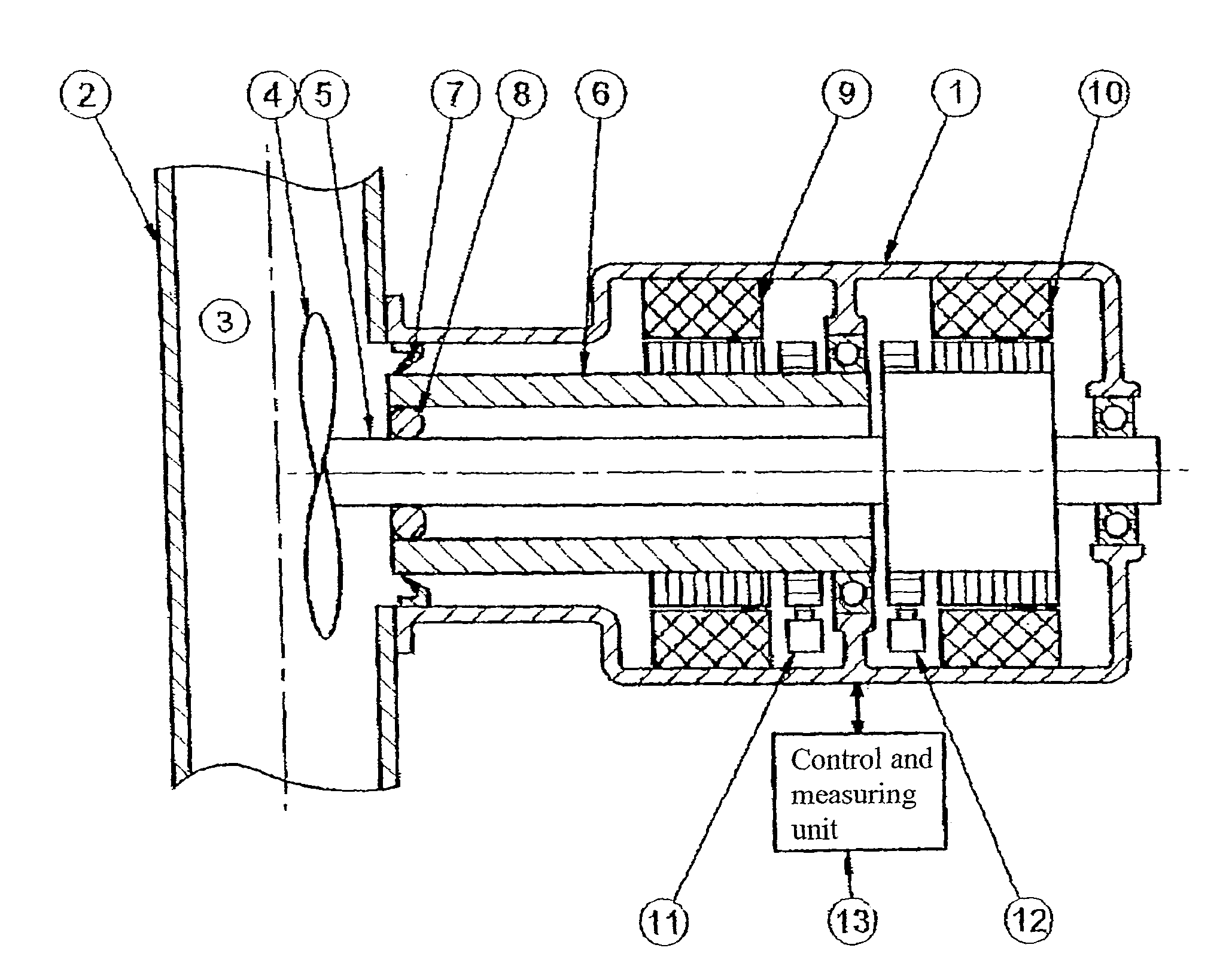
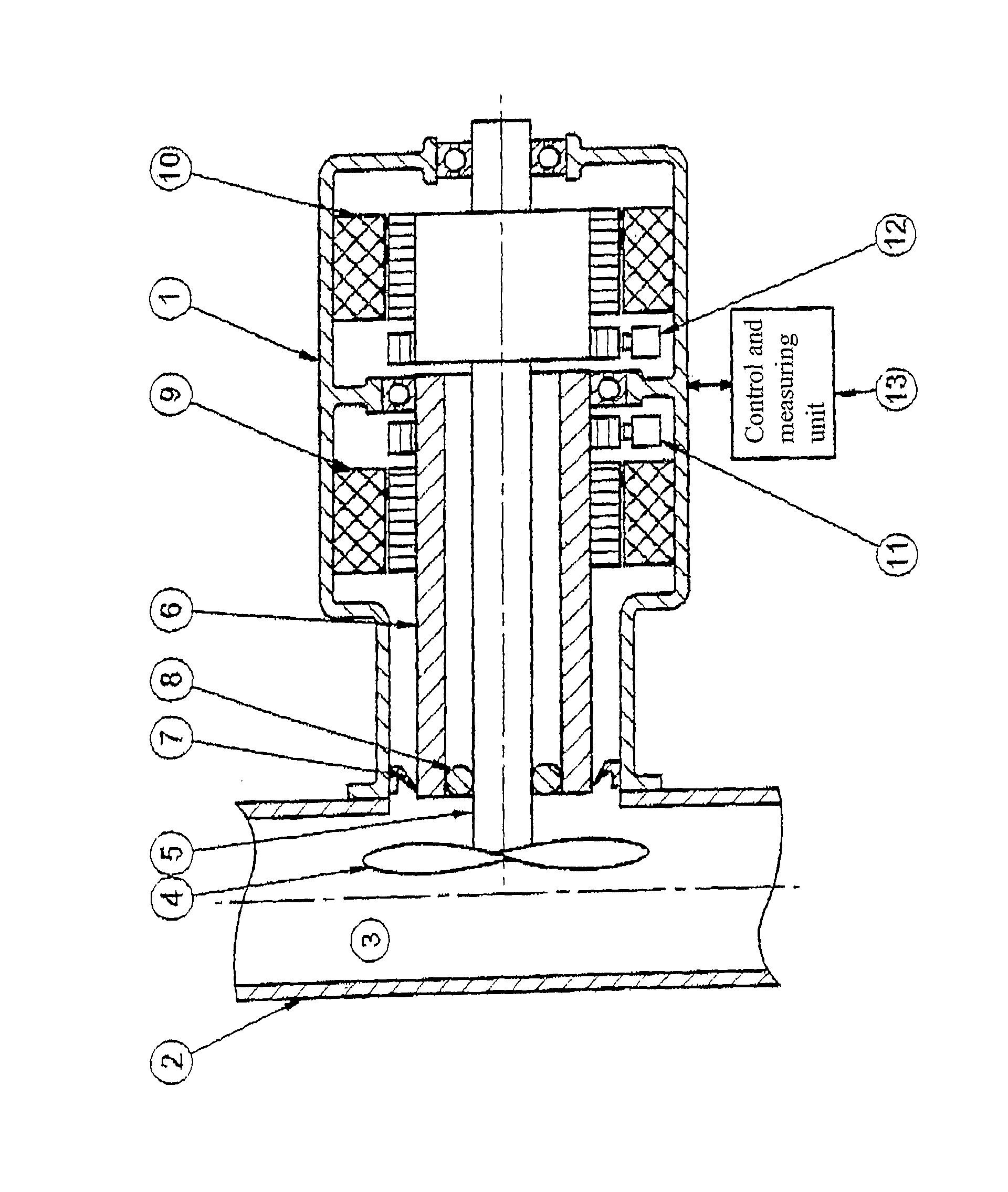
[0010]The present invention is described in greater detail below with assistance of a preferred embodiment under referral to the enclosed drawing.

[0011]In the drawing a schematic cross section through a torque measuring device 1 is shown, which is mounted on a process pipe 2 in which a measurement medium 3 flows passing a probe 4. Said probe 4 is fixedly attached to a measuring axle 5 in a dual axle system, which apart from the measuring axle 5 also comprises a hollow axle 6, which seals off the torque measuring device 1 from the measured medium 3 by means of a sealing 7. An elastic connection 8 between the hollow axle 6 and the measuring axle 5 permits the two axles 5, 6 to have a relative angular displacement at a change in the torque that the medium 3 exert on the probe 4.

[0012]The two axles 5, 6 is propelled independently by individual electrical motors 9, 10. The motor 9 propels the outer axle, i.e. the hollow axle 6, and the motor 10 propels the inner axle, i.e. the measuring ...


PUM

PropertyMeasurementUnit
torque measuringaaaaaaaaaa
viscosityaaaaaaaaaa
shearing forceaaaaaaaaaa

Abstract

A torque measuring device for determining properties such as viscosity, shearing force or concentration in liquids or suspensions. The device comprises two elastically connected concentric axles in the form of one external hollow axle through which an inner measuring axle extends, and an element responsive to the measured medium located on a distal end of the measuring axle. The axles are individually propelled by electrical motors. The motors are operated such that the axles rotate at generally constant speed and, simultaneously, the phase between the two are controlled irrespective of applied speed and torque. The torque is measured through the degree of load of the motor propelling the inner axle, which is provided as an output signal.

Description

[0001]The present invention relates to a device for, or more specifically, a principle for torque measuring devices or gauges, for measurement of for example pulp concentration, viscosity, dryness and rheological characteristics, which operates in accordance with the principle of force balance.BACKGROUND OF THE INVENTION[0002]Revolving measuring devices for concentration, shearing force, viscosity, dryness, rheological characteristics etc. have been in use for a long time in the process industry. The measuring devices are engineered after well established principles that in some cases date back to the 1960's. The fundamental principle is that a probe is rotated in a medium and the resistance torque that arise at the probe or sensor, as it is frequently called, is measured and transformed into a suitable out signal.[0003]The most frequently occurring design is the principle with a dual axle system which measures the angular difference between two concentric axles, wherein the outer h...

Claims


Application Information

Patent Timeline
Patent Type & Authority Patents(United States)
IPC IPC(8): G01N11/14
CPCG01L3/10G01N33/34G01N11/14H02P5/56G01L3/00G01N15/06G01N33/343
Inventor ANDERSSON, NICLASKULLANDER, JOAKIMLUNDBERG, PETERADRIAN, PETER
Owner BTG PULP & PAPER SENSORS
Why Eureka
Try Eureka