
Sequencer with async SIMD array

a sequencer and array technology, applied in the field of computer graphics, can solve the problems of still large amount of data manipulation to be done, large memory bandwidth, and large amount of polygons, so as to avoid sequencer stalls, hide memory latency, and avoid sequencer stalls

Inactive Publication Date: 2012-03-27
RPX CORP
View PDF51 Cites 44 Cited by
  • Summary
  • Abstract
  • Description
  • Claims
  • Application Information

AI Technical Summary

Benefits of technology

[0009]There are different ways to add complexity to a 3D scene. Creating more and more detailed models, consisting of a greater number of polygons, is one way to add visual interest to a scene. However, adding polygons necessitates paying the price of having to manipulate more geometry. 3D systems have what is known as a “polygon budget”, an approximate number of polygons that can be manipulated without unacceptable performance degradation. In general, fewer polygons yield higher frame rates.
[0015]Very long instruction word (VLIW) instructions explicitly specify several independent operations. Because VLIW instructions explicitly specify parallelism, it is not necessary to reconstruct parallelism from a serial instruction stream. VLIW architectures aim to reduce stalls by having the microcode instruction wide enough so that sequencer and ALU operations can be expressed in the same instruction, but this does not help with other sources of delay.
[0017]In addition to avoiding sequencer stalls, it is also desirable to hide the latency of memory accesses—global and instruction cache misses, but more importantly texture accesses that can take 100+ cycles to resolve. One way to hide this latency is to run the programs multi-threaded. In graphics, the same program is run on many pixels so if the program stalls because of a memory read for one set of pixels, the program can be switched to run on another set of pixels, and so on. With enough threads, memory latency can be hidden. The sequencer detects if the current thread is about to access a register with an outstanding load from memory (or an instruction or global cache miss) and will switch to running another thread that can do useful work. Thread-switching must be extremely light weight, i.e. computationally cheap, as switching threads is expected every few cycles. Therefore, the cost should ideally be zero sequencer cycles, but in practice, it takes 2 cycles because of the pipelining. ‘Few’ is typically 4 to 8 cycles, but this depends purely on the program that has been loaded. Accordingly, the system cannot afford to have the SIMD array idle while switching threads.Sequencer with Async SIMD Array
[0018]The present application describes a 3D graphics architecture in which a FIFO buffer is placed between the sequencer and the processing elements (PEs). The sequencer and PEs are not designed to run in lock step: instead the sequencer and PEs are decoupled to allow the PEs, which form the SIMD array, to run at 100% efficiency even when the sequencer is switching between threads and performing other flow control operations. Thus, the rate of instruction processing in the PE is not coupled to the rate of instruction processing in the sequencer. As a result, the PE and sequencer can be asynchronous. The PE and sequencer are logically asynchronous, i.e. decoupled, in that they do not have to work on the same instruction at the same time, but as an implementation convenience, they run in the same clock domain so technically they are physically synchronous.
[0019]The disclosed innovations, in various embodiments, provide one or more of at least the following advantages:

Problems solved by technology

However, even after these transformations and extensive calculations have been done, there is still a large amount of data manipulation to be done: the correct values for EACH PIXEL of the transformed polygons must be derived from the two-dimensional representation.
The most challenging 3D graphics applications are dynamic rather than static.
However, adding polygons necessitates paying the price of having to manipulate more geometry.
Achieving an adequately high rate of texturing and fill operations requires a very large memory bandwidth.
Sequencer operations other than simple increment can cause stalls and prevent the ALUs from running at maximum efficiency.
VLIW architectures aim to reduce stalls by having the microcode instruction wide enough so that sequencer and ALU operations can be expressed in the same instruction, but this does not help with other sources of delay.
Accordingly, the system cannot afford to have the SIMD array idle while switching threads.

Method used


Image

  • Sequencer with async SIMD array
  • Sequencer with async SIMD array
  • Sequencer with async SIMD array

Examples


Embodiment Construction

[0036]The numerous innovative teachings of the present application will be described with particular reference to the presently preferred embodiment (by way of example, and not of limitation).

P20 Architecture

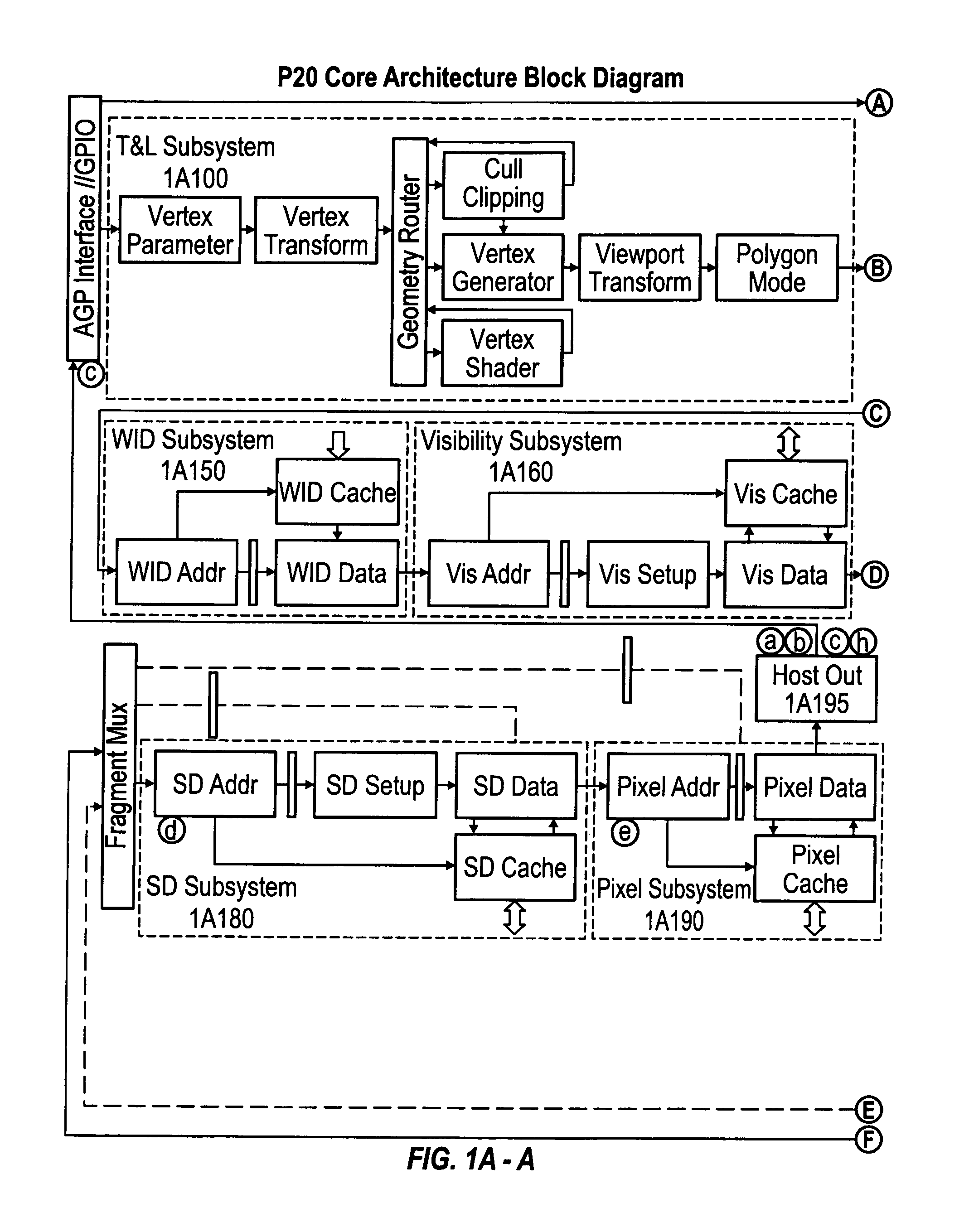
[0037]The following description gives details of a sample embodiment of the preferred rendering accelerator chip of the present innovations (referred to as “P20” in the following document, although not all details may apply to every chip revision marketed as P20). The following description gives an overview of the P20 Core Architecture and largely ignores other important parts of P20 such as GPIO and the Memory subsystem.

[0038]P20 is an evolutionary step from P10 and extends many of the ideas embodied in P10 to accommodate higher performance and extensions in APIs, particularly OpenGL 2 and DX9.

[0039]The main functional enhancements over P10 are the inclusion of a binning subsystem and a fragment shader targeted specifically at high level language support.

[0040]The P20 architect...


PUM


Abstract

A 3D graphics architecture in which a buffer is placed between the sequencer and the processing element (PE) array. The sequencer and PE array are not designed to run in lock step: instead the sequencer and PE array are decoupled to allow the PEs to run at 100% efficiency even when the sequencer is switching between threads and performing other flow control operations. Thus, the rate of instruction processing in the PE array is not coupled to the rate of instruction processing in the sequencer.

Description

CROSS-REFERENCE TO RELATED APPLICATIONS[0001]This application claims priority from U.S. Provisional Application 60 / 533,736 filed Dec. 31, 2003, which is hereby incorporated by reference.FIELD OF THE INVENTION[0002]The present inventions relate to computer graphics and, more particularly, to a computer graphics rendering architecture.BACKGROUND AND SUMMARY OF THE INVENTIONBackground: 3D Computer Graphics[0003]One of the driving features in the performance of most single-user computers is computer graphics. This is particularly important in computer games and workstations, but is generally very important across the personal computer market.[0004]For some years, the most critical area of graphics development has been in three-dimensional (“3D”) graphics. The peculiar demands of 3D graphics are driven by the need to present a realistic view, on a computer monitor, of a three-dimensional scene. The pattern written onto the two-dimensional screen must, therefore, be derived from the three...

Claims


Application Information

Patent Timeline
IPC IPC(8): G06F15/00
CPCG06F9/3879G06F9/3889G06T15/005
Inventor BALDWIN, DAVID R.
Owner RPX CORP
Learn More