
Device and methods for biphasic pulse signal coding

a pulse signal and coding technology, applied in the field of pulse signal coding, can solve the problems of consuming a/d converters, severely restricting the performance of data acquisition devices, and limiting the power and bandwidth of many data acquisition devices, so as to achieve the effect of easy extension of coding

Active Publication Date: 2012-03-20
UNIV OF FLORIDA RES FOUNDATION INC
View PDF45 Cites 4 Cited by
  • Summary
  • Abstract
  • Description
  • Claims
  • Application Information

AI Technical Summary

Benefits of technology

The invention provides a way to encode time signals using a unique sampling technique based on asynchronous biphasic pulses. This technique overcomes limitations of conventional devices used to record analog signals and process them digitally. The asynchronous biphasic pulse train generated by this technique can be transmitted more robustly relative to analog signals and can be used to reconstruct the original analog signal using a more sophisticated signal reconstruction algorithm. The technique can also reduce data bandwidth needed for signal transmission and can be used in applications that require front-end circuitry with ultra-low power requirements. The invention also introduces a refractory period to manage sampling and allows more channels to be simultaneously recorded. Overall, the invention provides a more efficient and effective way to encode time signals.

Problems solved by technology

Many data acquisition devices, however, are severely constrained in terms of available power and available bandwidth.
Therefore, the use of a power-consuming A / D converter can be a further constraint on the performance of such devices.
For example, a limitation regarding A / D converters belonging to the widely-used Nyquist-Rate class of converters, which are characterized by a one-to-one correspondence between an output value and a single input value, is their power consumption.
Moreover, when scaled to submicron size, high-resolution analog circuits are affected by low-power supply and poor transistor output resistance, the latter effect being due to the well-known body effect.
Thus, a continuing challenge for designers is how to decrease power consumption in devices that record analog signals but perform signal processing digitally.
Yet the high resolution in time typically requires a high-speed clock, which results in high power consumption and increased complexity in the digital circuitry employed.
Moreover, Delta-Sigma converters tend not to be well suited for systems such as implanted neural recording devices given the typical power and die area constraints often imposed on such devices.
The diminished suitability of Delta-Sigma converters stems from certain unique features of signals such as neural action potentials and speech signals.
Overall power will be wasted since the signal has to be shifted up by a worst-case offset, which is the most negative signal value possible during operation of the device.
A problem with this approach is that the DC bias tends to continuously produce spikes in the signal even when the original signal is in an idle state during which there is no useful information conveyed by a sensed signal.
However, an additional problem of the IF signal representation is that the peak firing rate is unbounded.
The extra pulses lead to wasted power consumption, wasted data bandwidth, and further problems in multiplexing the data off-chip.
This results in the peak firing rate being limited by the inverse of the refractory period.

Method used


Image

  • Device and methods for biphasic pulse signal coding
  • Device and methods for biphasic pulse signal coding
  • Device and methods for biphasic pulse signal coding

Examples


examples

Synthetic Signal Simulation

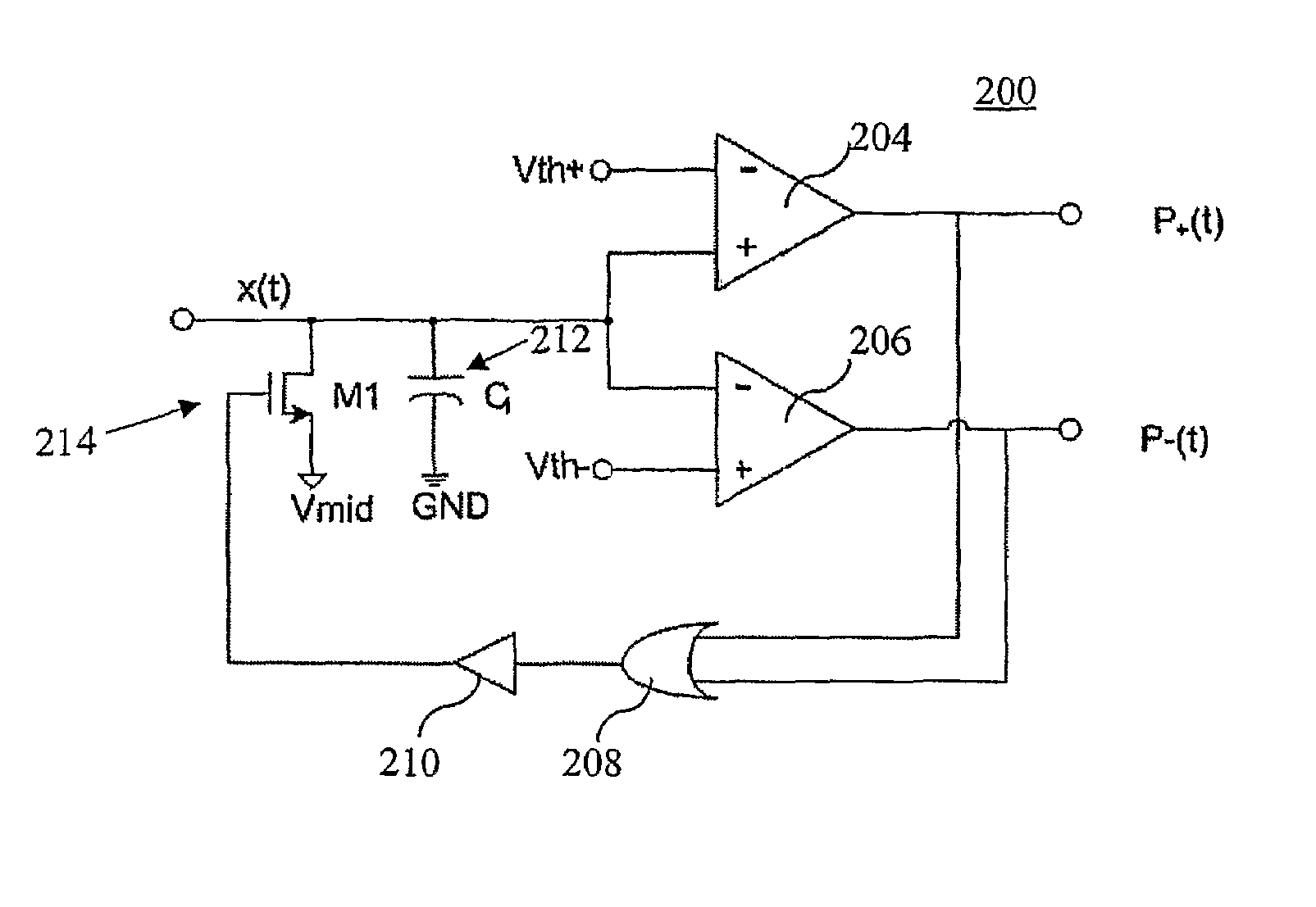
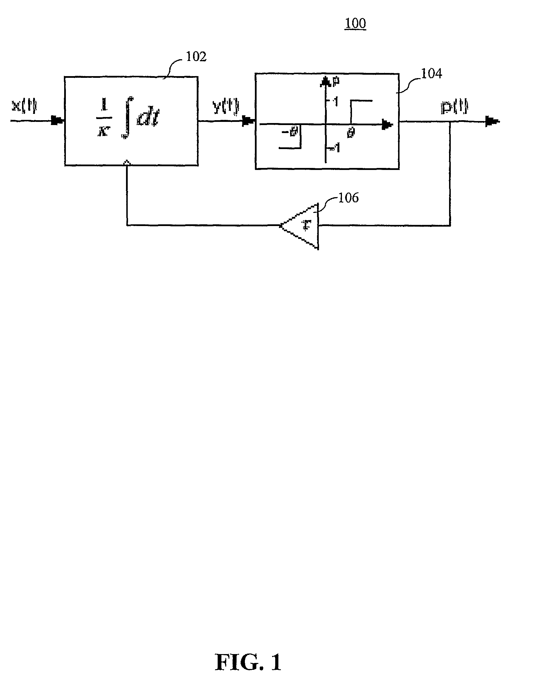
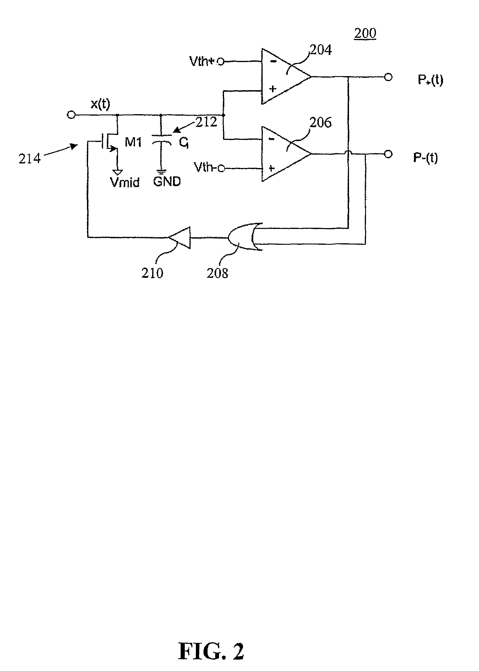
[0075]The invention can be demonstrated by the results of synthetic signal simulation, where the synthetic signal is defined as a superposition of admissible frequencies with random amplitude. In FIG. 4(a), the bandwidth of an input signal is 5 KHz. The threshold θ is 5.6×10⁻⁵. The corresponding output pulse train with the maximum timer interval δ is 95.7 μs. The total number of pulses is 157. FIG. 5(a) shows the recovery results based on the above-described iterative algorithm. The error, in FIG. 5(b), is defined here as the difference between the original signal and the recovered signal:

el(t)=x(t)−xl(t).

[0076]The signal-to-error ratio (SER) is the power ratio between the original signal and the recovered signal. The SER can be used to evaluate the convergence performance. According to the previous equation for the error, the slope of the SER should be approximately equal to 0.38 dB per iteration. FIG. 6 demonstrates the agreement of the results with the ...


PUM


Abstract

A method for coding time signals based on generating an asynchronous biphasic pulse train is provided. The method includes generating response signals based upon one or more input signals. A pulse comprises a positive pulse if a voltage of the response signal is greater than a predetermined positive voltage threshold. A pulse comprises a negative pulse if the voltage of the response signal is less than a predetermined negative voltage threshold. The method further includes a method for the reconstruction of a uniformly sampled version of the original signal.

Description

CROSS-REFERENCE TO RELATED APPLICATIONS[0001]This application is a §371 national stage entry of International Application No. PCT / US2006 / 030886, filed Aug. 8, 2006, which claims the benefit of U.S. Provisional Application No. 60 / 706,415, filed Aug. 8, 2005, both of which are hereby incorporated by reference.FIELD OF THE INVENTION[0002]The present invention is related to the field of electronic signal processing, and, more particularly to pulse signal coding.BACKGROUND OF THE INVENTION[0003]Recorded sensor signals of many electronic devices, including implanted medical devices and remote sensors, are analog in nature, but post-recordation processing of the signals is typically performed using digitally based algorithms. Thus, the analog signals must frequently be converted into digital form prior to applying signal processing algorithms. Digital signals provide other advantages relative to analog signals. For example, digital signals are generally more robust to transmit and typicall...

Claims


Application Information

Patent Timeline
Patent Type & Authority Patents(United States)
IPC IPC(8): H04L27/00
CPCH03K7/06H03M1/125H03M3/00H03M5/02H04L25/49G06N3/049
Inventor CHEN, DUHARRIS, JOHN G.PRINCIPE, JOSE C.
Owner UNIV OF FLORIDA RES FOUNDATION INC
Learn More