
Hydrogen purifier module and method for forming the same

a technology of hydrogen purifier and module, which is applied in the direction of non-electric welding apparatus, furniture joining, fastening means, etc., can solve the problems of reducing the hydrogen permeability, reducing the purity of supplied hydrogen, and having certain inherent limitations

Active Publication Date: 2012-02-07
JIANGSU QINGNENG NEW ENERGY TECHNOLOGIES CO LTD +1
View PDF19 Cites 5 Cited by
  • Summary
  • Abstract
  • Description
  • Claims
  • Application Information

AI Technical Summary

Benefits of technology

"The present invention relates to a method for sealing a hydrogen purifier using a low temperature melting element or alloy. The sealing process involves heat treatment at low temperatures to prevent unwanted metallurgical changes in the purifier membrane and interdiffusion from the support substrate. The invention allows for careful tailoring of the alloy and thickness of the resulting liquid layer during heat treatment, as well as limiting the location of the plated materials to selected areas to prevent compromise of the membrane. The technical effects of the invention include improved sealing efficiency, reduced membrane damage, and improved purifier performance."

Problems solved by technology

Thinner foils may be used, but they are more fragile and prone to pinhole leaks, which degrades the purity of the supplied hydrogen.
At these high temperatures, however, significant interdiffusion between the support and the membrane is expected to lower the hydrogen permeability.
While all of the above examples allow for the fabrication of membrane purifiers, each has certain inherent limitations.
Small surface imperfections in the form of high or low spots, or scratches, which are typically present, make it very difficult to form a hermetic seal.
However, brazing has two drawbacks.
First, the high processing temperatures required to melt the braze can cause intermetallic diffusion to occur between a metallic membrane and the membrane support, as well as alteration of the crystal structure of the membrane.
For example, processing Pd60Cu40 membranes above 400° C. for any length of time can cause permanent phase separation of the alloy, forming copper-rich regions, which destroys the hydrogen permeability of the material.
Second, there is the risk that the brazing materials may contact the membrane, forming unwanted alloys while consuming the membrane.
In some cases the braze material in contact with the membrane will actually cause perforations in the membrane.
This stress may cause eventual rupture and leakage of the seals after cycling the purifier thermally or with hydrogen a number of times. It is also difficult to form a welded seal on materials as thin as a 25 micron membrane, when the other materials (i.e., stainless steel parts, etc.) are much thicker.

Method used


Image

  • Hydrogen purifier module and method for forming the same
  • Hydrogen purifier module and method for forming the same
  • Hydrogen purifier module and method for forming the same

Examples


example 1

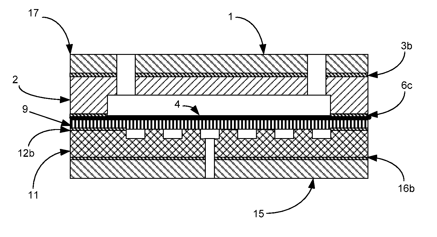
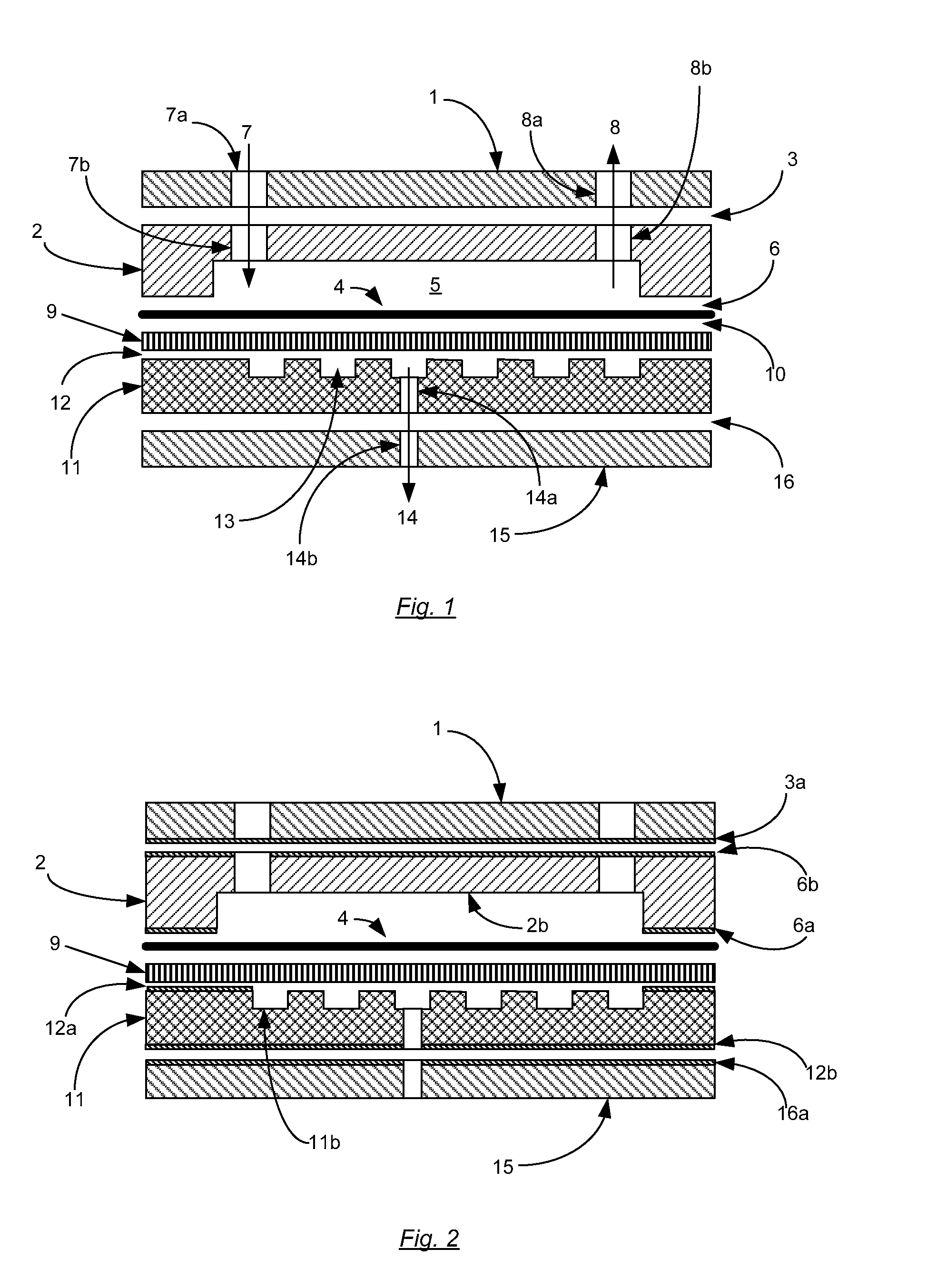
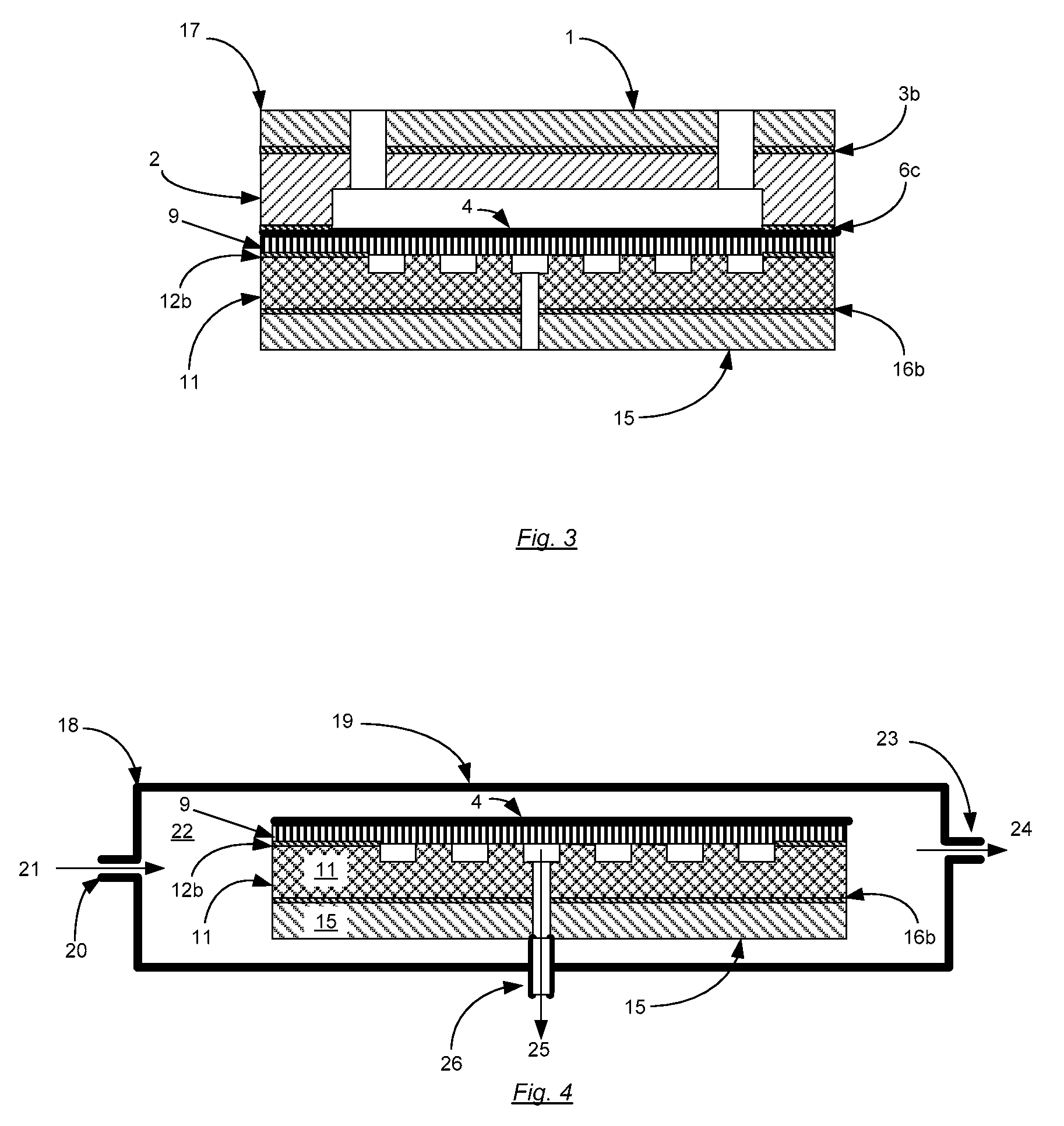
[0052]8 microns of silver were electroplated on a nickel strike on 304 stainless steel parts which define the permeate cavities (“hydrogen collector”), after which 1 micron of tin was electroplated over the silver plating at the perimeter of the parts by using a masking agent to prevent plating at the interior portion of the parts. Two end plates made of 304 stainless steel were also similarly plated with 2 microns of tin over 8 microns of silver on a nickel strike. A thin plating of gold on nickel strike was plated on 304 stainless steel parts which define the pressurized gas cavities (“raffinate plates”). Electrochemically etched 304 stainless steel screens were also plated with gold on nickel strike.

[0053]Four Pd60Cu40 membranes (25 microns thick, active area approximately 88 cm2) were placed into a compressed assembly in the order of: end plate-4×(raffinate plate / membrane / screen / hydrogen collector)-end plate. The assembly was heated to 400° C. in a reducing atmosphere for 8 hour...

example 2

[0054]1 micron of tin was plated over 6 microns of silver (on a nickel strike) via selective plating at the perimeter of a 304 stainless steel hydrogen collector and raffinate plate. Once the parts were plated the solvent-based plating barriers were removed with acetone.

[0055]Two end plates made of 304 stainless steel were plated with 2 microns of tin over a nickel strike. An electrochemically etched 304 stainless steel screen was also plated with gold on nickel strike.

[0056]One Pd77Ag23 membrane (31 microns thick, active area approximately 88 cm2) was placed into a compressed assembly in the order of: end plate-raffinate plate-membrane-screen-hydrogen collector-end plate. The assembly was heated to 550° C. in a reducing atmosphere for 5 hours. A transient liquid phase bond was formed between all the parts except the membrane and screen, which formed a sealing diffusion bond at the perimeter. After the heat processing step, all of the seals were found to be free of leakage, and no l...


PUM

PropertyMeasurementUnit
melting temperatureaaaaaaaaaa

Abstract

A hydrogen purifier utilizing a hydrogen permeable membrane, and a gas-tight seal, where the seal is uses a low temperature melting point metal, which upon heating above the melting point subsequently forms a seal alloy with adjacent metals, where the alloy has a melting point above the operational temperature of the purifier. The purifier further is constructed such that a degree of isolation exists between the metal that melts to form the seal and the active area of the purifier membrane, so that the active area of the purifier membrane is not corrupted. A method of forming a hydrogen purifier utilizing a hydrogen permeable membrane with a seal of the same type is also disclosed.

Description

[0001]This invention was made with Government support under DE-FG02-06ER84535 awarded by the Department of Energy. The Government has certain rights in this invention.FIELD OF THE INVENTION[0002]The present invention generally relates to a hydrogen purifier utilizing a hydrogen-permeable membrane to purify hydrogen from mixed gases containing hydrogen. A purifier module with improved sealing means is described where the seals are formed by first melting a metal with a low temperature melting point, and then allowing the metal to form a subsequent alloy which has a melting temperature above the operational temperature of the purifier.BACKGROUND OF THE INVENTION[0003]Hydrogen purifiers are devices that separate hydrogen from hydrogen-rich gaseous mixtures, providing a pure stream of hydrogen for a variety of uses. Typical applications include supplying hydrogen for fuel cells from reformed gases, purifying commercial grade hydrogen to provide for ultra-pure hydrogen used for semicondu...

Claims


Application Information

Patent Timeline
Patent Type & Authority Patents(United States)
IPC IPC(8): B01D53/22B01D67/00
CPCB01D53/22B01D63/08B01D65/003C01B3/505C01B3/503B01D2313/04B01D2313/42Y10T403/479C01B2203/0405C01B2203/047Y10T403/478
Inventor DEVRIES, PETER DAVID
Owner JIANGSU QINGNENG NEW ENERGY TECHNOLOGIES CO LTD
Learn More