Eureka AIR delivers breakthrough ideas for toughest innovation challenges, trusted by R&D personnel around the world.

Multiple light-source illuminating system

a light source and illumination system technology, applied in outdoor lighting, lighting applications, lighting heating/cooling arrangements, etc., can solve the problems of insufficient spatial flexibility of lighting systems, deleterious effects on color quality of lighting, and process that involves cost and inefficiencies in redirecting light, etc., to achieve convenient configuration, high lumen output, and high current capacity

Inactive Publication Date: 2012-01-24
SPERO YECHEZKAL EVAN
View PDF13 Cites 265 Cited by
  • Summary
  • Abstract
  • Description
  • Claims
  • Application Information

AI Technical Summary

Benefits of technology

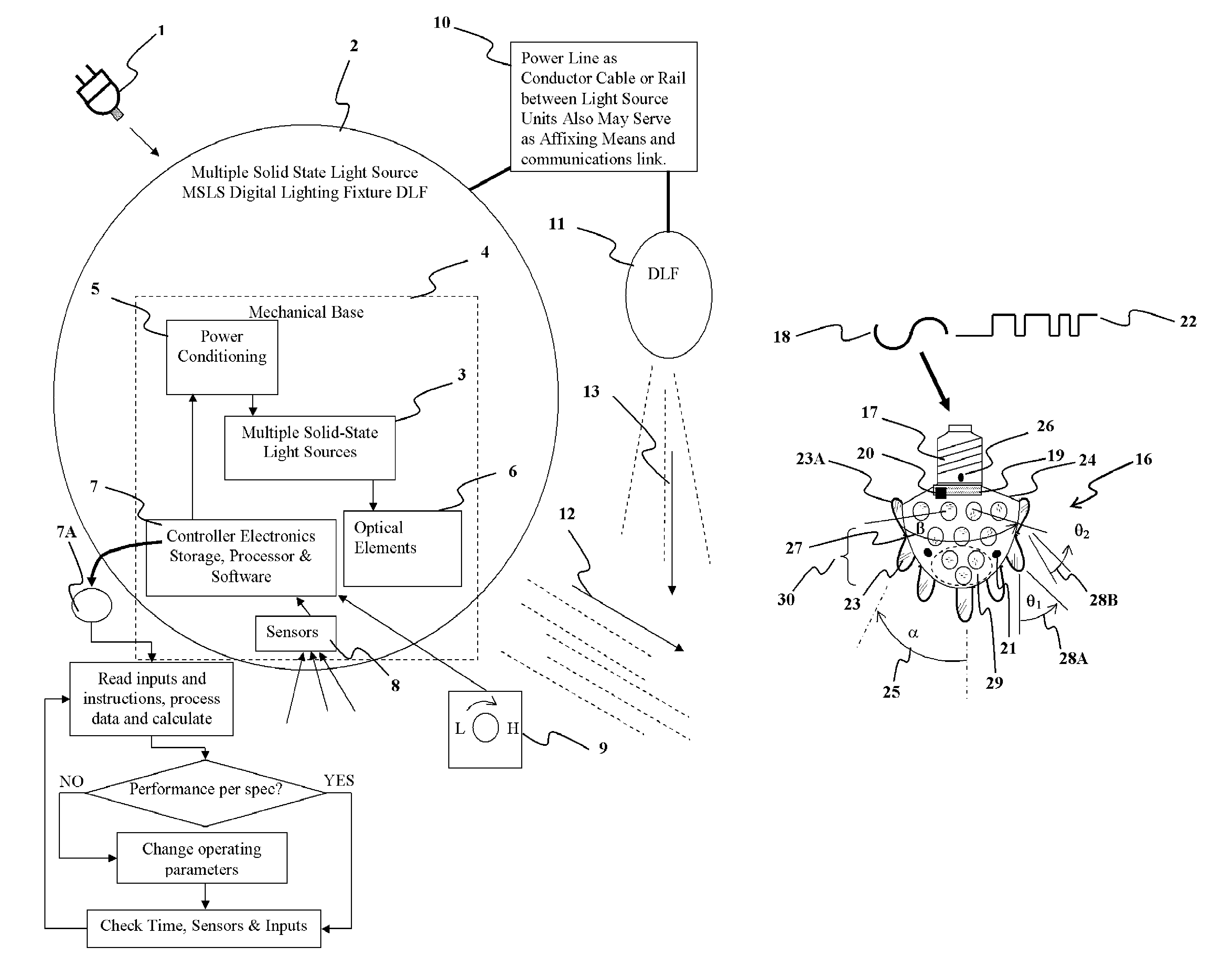
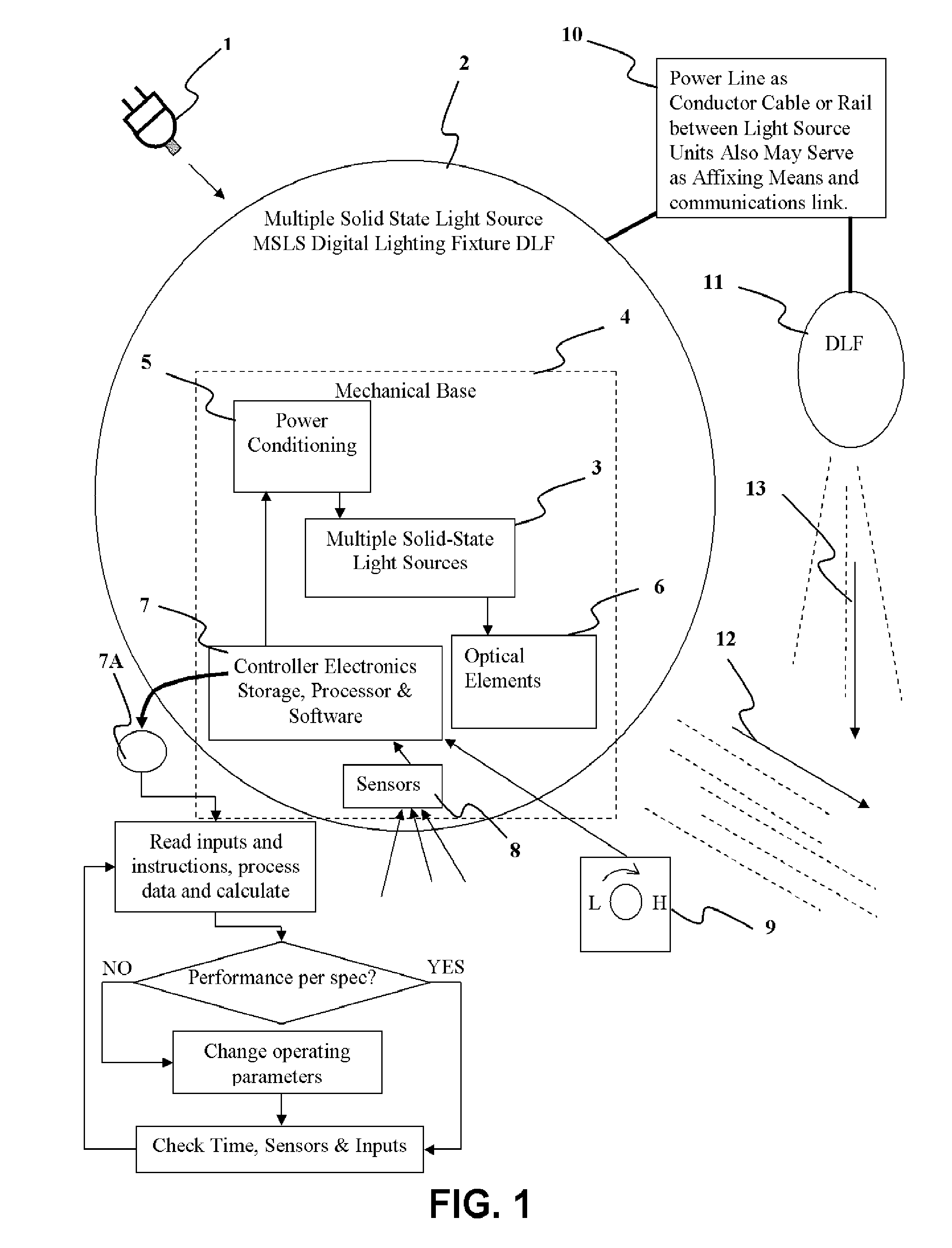
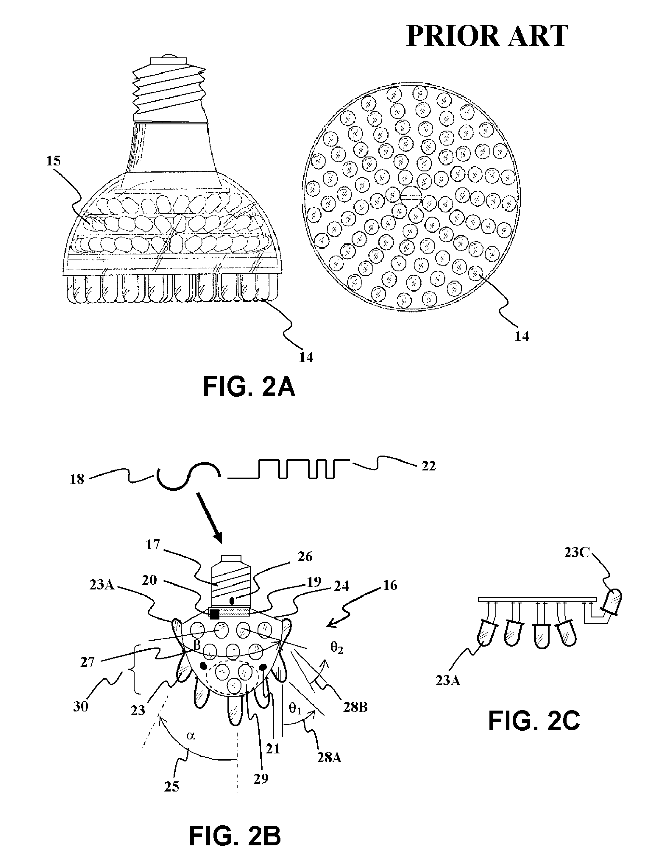
[0047]The present invention provides a unique approach to solid-state illuminating devices that is a departure from conventional prior art LED lighting practice. Prior-Art LED lighting technology manufacturers have been taking LED junctions and packaging them in evermore-powerful configurations to carry out the function of lamps. These LED lamps are teamed with reflectors and / or refractors similar to the techniques practiced with standard lamps or put on strips which is just another way of distributing the light over the area to be illuminated. This invention comprises a different approach which is to provide the end user with the most correct lighting solution not a new technology lamp to replace the old one. The present invention comprises a novel multi-light source approach to the design and construction of solid-state lighting fixtures (vs. solid-state lamps), which is termed a “Digital Lighting Fixture”, due to the control of individual lighting element “digits” to provide the “correct” lighting solution for the situation at hand.
[0048]The invention embraces LED-illuminating devices covering a wide scope of applications including a room light and step light design as well as the general method for designing solid state luminaires from ground up from indoor to outdoor use in residences, factories, stores stadiums and streets. The general concept allows anyone to build a lighting fixture from the ground up, tailor made to the final application rather than building a fixture around a common lamp. This is because it difficult to control the high temperature processes of incandescent and discharge lamps. In addition it takes a tremendous amount of investment in tooling to manufacture an incandescent, fluorescent or HID lamp. Electronic components on the other hand are made of large quantities of discrete components which are masked or robotically placed on to substrates. These smaller building blocks can then be easily configured per specific applications.
[0049]This disclosure also teaches that when it comes to solid-state lighting big is not necessarily better. The approach of LED manufacturers trying to get into the lighting business by attempting to replicate the effect of present day lamps has been to make large, high current capacity, high lumen output electroluminescent junctions having marginally acceptable lighting characteristics. Lumileds Luxeon® DS25 Emitter running at 350 mA is an example of such an approach. In a few years manufacturers have raised currents from 50 mA to above 500 mA, at the time of this writing. These advances are certainly favorable at reducing costs and making LEDs a practical light source but attempting to get 1000 lumen (equivalent to a 60 W incandescent lamp) is not necessarily the best path to take, especially if it comes at the price of light conversion or distribution efficiency. In contrast to a prior art, single large, lamp replacement like light source, the present invention provides multiple, small sized sources of differing characteristics such that the effect of the whole is greater than the sum of the individual parts. The determining size factor then becomes when is there a sufficient progression of values varying by minute degrees or continuum so as be non-discernable or irrelevant to the user. That is, LEDs are generally of a single wavelength (color, frequency), have small optics close in to the individual light sources since they operate coolly, and have stable conversion efficiency over a wide range of currents and light output. The added controllability offered by breaking the total light output up into discrete (“digital”) specifically aimable and dimmable elements which can be addressed by control electronics to effect intensity, spectrum and spatial distribution of intensity and spectrum, yields a lighting fixture (vs. lamp) of unparalleled performance. Unique to this patent is the approach. It is the approach of a lighting manufacturer who provides lighting solutions versus that of a lamp manufacturer who produces a generic lamp.
[0050]The advance over prior art is a solid-state light source with increased: 1. Efficiency—more effective lumen per watt electricity. 2. Durability—physical strength, life expectancy, lumen maintenance and spectral stability. 3. Lighting quality—as related to visual comfort and “atmosphere”. 4. Functionality—ability to control the light placement, intensity and color temperature and do so as needed. 5. Energy savings 6. Lower overall lifecycle cost
[0051]Integrating the light source with power conditioning electronics, control circuitry and sensors gives additional cost benefits and functionality including: 1. Mass production capability 2. Sealed-for-life fixture 3. Exact optical performance less spill light 4. Compact design 5. Feedback control and recalibrated color consistency over the device lifetime 6. Real-time lighting needs adaptability.
[0052]Therefore, it would be advantageous to have a luminaire that require no maintenance, has smoothly controllable light output in terms of intensity, spectra, spatial distribution, is robust, mass producible as a single unit, factory sealed against the elements, is self calibrating over its lifetime, is adaptable to changing requirements, works on high or low voltage, has an affixation apparatus and is aesthetic.

Problems solved by technology

This is a process that involves cost and inefficiencies in redirecting the light.
Examples of the inflexible prior-art approach based on today's designs include: lighting is often provided in rooms where daylight contributes significantly to the overall lighting level or in areas near the window but the lighting system is not flexible enough spatially to take advantage of the daylight contribution and reduce power; or the lighting is always on at maximum power irrespective of whether or not there is activity in the room to justify the lighting level.
Even when external dimming controls are provided to the lighting fixture, the color quality of the lighting is deleteriously affected.
At a lower lighting level a warmer color temperature is generally required and the luminaire lamp color is not adjustable.
When a new lamp source arrives generally they are placed into present-day lighting luminaire designs which are not optimal for the new light source.
Presently however, the high cost of lumen per watt appears to make LEDs uneconomical for most lighting applications.
Maintenance of prior-art luminaires in outdoor applications and the requirement for watertight resealing, increases fixture cost and complexity.
The dissimilarity of the manufacturing technologies, operating lifetimes and materials results in a multi-component fixture assembly held together by fasteners which don't lend themselves to mass production and the luminaires are not factory sealed for life.
Due to the physics involved in the light generation process, it is difficult at the source to gain control of the spatial light propagation.
A reflector lamp will partially control the emitted light which hits the reflector, but will not control the remaining light emanating from the filament or discharge tube.
Prior-art lamps are thus provided with bulky bases which fit into bulky sockets and do not lend themselves to being permanently wired into printed circuit boards or bonded onto electronic chips.
Correct lighting practice: A bare incandescent lamp illuminating a room is arbitrarily termed poor lighting practice.
The bare light bulb hooked up to the electric power via a light switch, causes glare, wastes light, delivering the light to useless areas, has no provision for dimming and is energy inefficient.
Approximately 80% of this is in energy costs.
The commodity being purchased is lighting, the major lifecycle cost is electricity.
This however, is still not what the customer is paying for.
Chances are, as experienced lighting designers know, that the light intensity, even in a good lighting design, is still not evenly distributed over the work surfaces.
This excess light, wasted energy as far as the customer is concerned, probably accounts for another 10% loss.
In general however the design process has not zeroed in on providing the correct lighting solution.
There is no combination of different light source characteristics to build a new combined light source characteristic and this is a lamp replacement not a LF fit for general illumination.
It also does not provide a method to handle color shift over the lifetime of the illuminating device.
Although this device includes the desirable communications control aspect, this device does not relate to a multi-light source capability which allows for the smooth variation lighting and its even distribution.
In many other stairwells and hallways the lighting is always left on wasting energy.
However, the present-day lamp or fixture is not designed to fully and efficiently take advantage of these new control capabilities.
This is because it difficult to control the high temperature processes of incandescent and discharge lamps.
In addition it takes a tremendous amount of investment in tooling to manufacture an incandescent, fluorescent or HID lamp.
This disclosure also teaches that when it comes to solid-state lighting big is not necessarily better.
These advances are certainly favorable at reducing costs and making LEDs a practical light source but attempting to get 1000 lumen (equivalent to a 60 W incandescent lamp) is not necessarily the best path to take, especially if it comes at the price of light conversion or distribution efficiency.

Method used


Image

  • Multiple light-source illuminating system
  • Multiple light-source illuminating system
  • Multiple light-source illuminating system

Examples


Embodiment Construction

[0073]The system is built around a “digital” light source. That is, the emanating lighting effect is the sum of the characteristics of a multiplicity of discretely controllable “digit” sources. The difference between the individual “digit” light sources and their summation manifests itself in the resultant light characteristic, be in its intensity, spatial intensity distribution, spectral energy content and spectral intensity distribution. All of these characteristics are also variable with time. A light source for this purpose may be electroluminescent such as a Light Emitting Diode (LED) junction, Organic Light Emitting Diode (OLED) or carbon-related field emission devices such as a nanotube-phosphor-combination, HID, fluorescent or even an incandescent source. While a one-source lamp will not have the flexibility to effect the most correct illumination characteristics, such as maintaining correct intensity and color temperature for the lighting task at hand over changing environm...


PUM


Abstract

A method and apparatus is provided for a multiple light-source illuminating device, the design and construction of which is derived from the lighting requirements of a specific lighting application. The resulting illuminating device (16) provides illumination according to the principles of lighting practice for the optimal performance of visual tasks. Coupling with sensors (21) and logical control (20) allows illumination intensity and spectrum to be varied according to changing user needs. The illuminating device includes multiple discrete light emitting components of different spatial intensity distribution and color spectrum mounted in specific orientations such that the application oriented combined lighting effect is created. The control is provided via a differentiated power supply (19) capable of affecting the current, voltage and duty cycle determining the relative contribution of each light source effecting a different spatial intensity distribution and color spectrum.

Description

CROSS REFERENCE TO RELATED APPLICATIONS[0001]This application claims benefit of U.S. provisional patent application Ser. No. 60 / 395,308 Jul. 12, 2002, titled: Multiple light source illumination system.BACKGROUND OF INVENTION[0002]1. Field of the Invention[0003]The present invention relates to multiple light source illuminating devices intended to replace incandescent, fluorescent and HID luminaries in general and specialty lighting applications.[0004]2. Background and Description of the Prior Art[0005]Prior art lighting practice utilizes an apparatus termed a luminaire or Lighting Fixture to provide illumination to indoor and outdoor living spaces, vehicles machinery etc for the performance of various visual tasks. A luminaire provides features other than just light which may include light distribution, shielding, man-machine-interfaces such as on / off switches, connection to power mains, apparatus for affixation to construction elements and aesthetics. A typical prior art luminaire ...

Claims


Application Information

Patent Timeline
Patent Type & Authority Patents(United States)
IPC IPC(8): F21V21/00F21V9/00B60Q1/04B60Q1/08B60Q1/14F21K99/00F21S4/00F21S8/00F21S8/10F21V21/02H05B37/02
CPCB60Q1/04F21V29/677B60Q1/1423F21S4/008F21V23/0471H05B33/0812H05B33/0857H05B33/0863H05B37/02F21K9/13F21V29/20F21V29/402F21V23/0435B60Q1/085B60Q2300/054B60Q2300/112B60Q2300/116B60Q2300/122B60Q2300/134B60Q2300/142B60Q2300/21B60Q2300/23B60Q2300/312B60Q2300/314B60Q2300/322B60Q2300/41B60Q2300/42F21S48/10F21V21/02F21W2101/10F21W2111/023F21W2111/027F21W2111/08F21W2131/103F21W2131/40F21Y2101/02F21Y2113/00Y02B20/383F21V14/08F21S4/28F21K9/23F21Y2115/10F21S41/663H05B45/395H05B45/20F21W2102/13F21S41/153F21V29/60F21V29/70Y02B20/30H05B47/17H05B47/165F21S41/141A01K1/00F21W2102/00F21S41/00
Inventor SPERO, YECHEZKAL EVAN
Owner SPERO YECHEZKAL EVAN
Why Eureka
Eureka Blog
Learn More