
Systems and methods for determining placement of virtual machines

Active Publication Date: 2012-01-17
AKORRI NETWORKS
View PDF13 Cites 88 Cited by
  • Summary
  • Abstract
  • Description
  • Claims
  • Application Information

AI Technical Summary

Benefits of technology

[0013]In a further aspect of the present invention, individual elements without a subsystem, such as storage adapters, storage processors, or switch ports, can be assigned and reassigned to service a set of virtual machines, in order to provide better balance across the entire system.
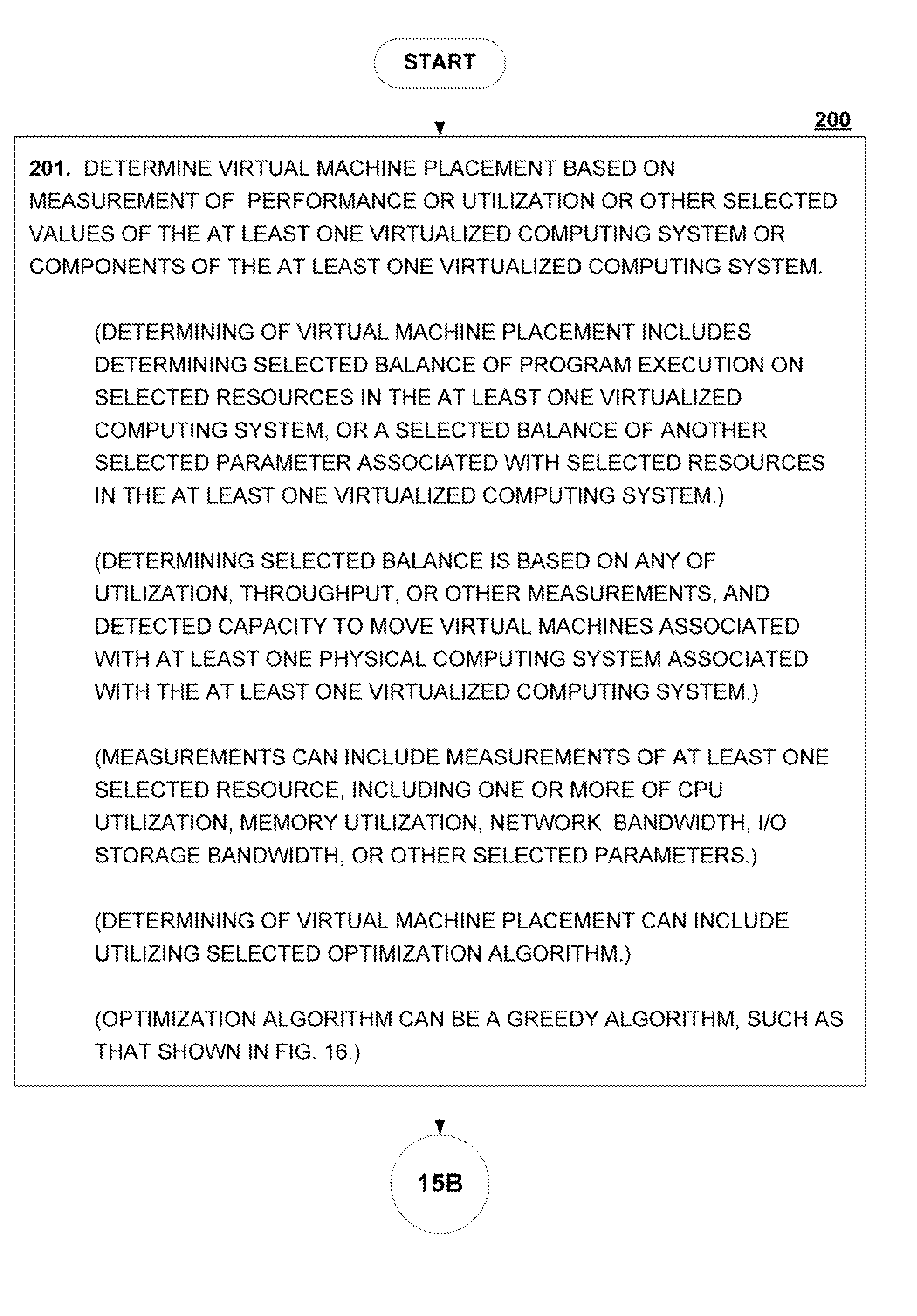
[0014]A further aspect of the present invention relates to the efficiency of the selected placement selection algorithm. As a general matter, to arrive at the best possible configuration, typically all possible virtual machine placements would need to be explored. However, for improved efficiency and resource utilization, one implementation of the invention described herein presents a “Greedy Algorithm” approach, which leads to a result close to the optimal placement in most cases. Moreover, the use of a “Greedy Algorithm” allows this placement algorithm to be applied repeatedly and frequently, without overwhelming system resources.
[0020](2) assigning or reassigning individual elements of the computing system to service a set of virtual machines, to provide improved balance across the at least one virtualized computing system, based on selected utilization or throughput values, or other selected values, the utilization or throughput values comprising use of any of processors, memory, networks and input / output resources, the individual elements comprising any of storage adapters, processors, or switch ports; and / or

Problems solved by technology

Any one of the programs sharing the computing resources can impede the performance of any other program, unless a policy is in place that allows the effective sharing of resources.
However, when virtualization is utilized, it becomes more difficult to balance system resources.
The VMM is thus tasked with maintaining balance between the multiple virtual machines running on the shared system resources, but in typical, conventional virtualized computing environments, the ability of the VMM to achieve such a balance is compromised.

Method used


Image

  • Systems and methods for determining placement of virtual machines
  • Systems and methods for determining placement of virtual machines
  • Systems and methods for determining placement of virtual machines

Examples


Embodiment Construction

[0042]The following Detailed Description is organized into the following sections:

[0043]A. Introduction

[0044]B. Virtual Machine Placement in Accordance with the Invention

[0045]C. Examples of the Present Invention

[0046]D. General Techniques in Accordance with the Invention

[0047]E. Digital Processing Environments in Which the Invention Can Be Implemented

[0048]F. Conclusion

A. Introduction

[0049]Described herein are methods and systems that enable more efficient load balancing in virtualized computing systems. According to the described methods and systems, the current load / performance of components or subsystems in a virtualized computing system are evaluated or measured, and the performance measurements are utilized to determine an optimized placement or movement of virtual machines within the virtualized computing system. The described methods and systems thereby provide better balance within the virtualized system.

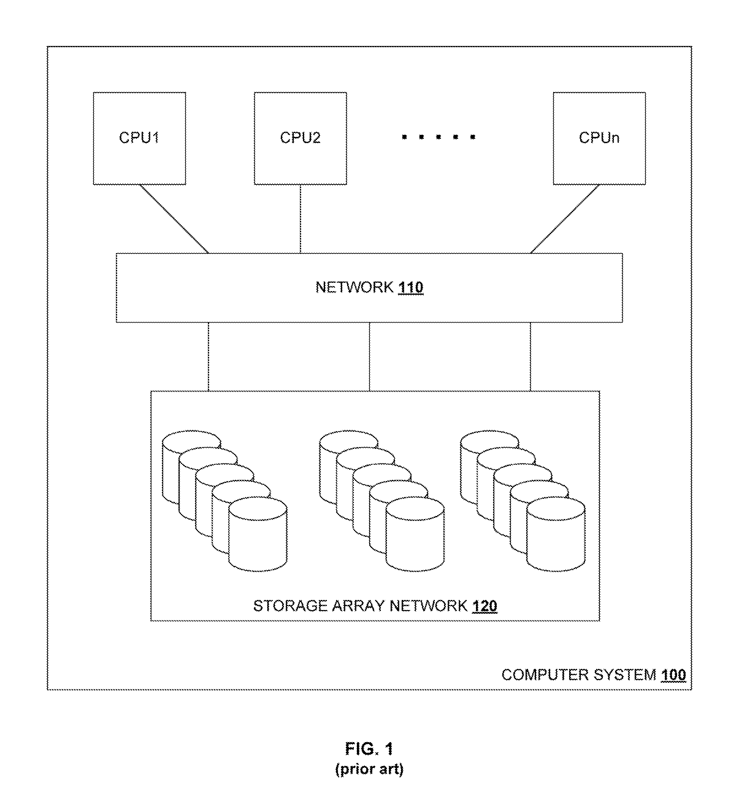
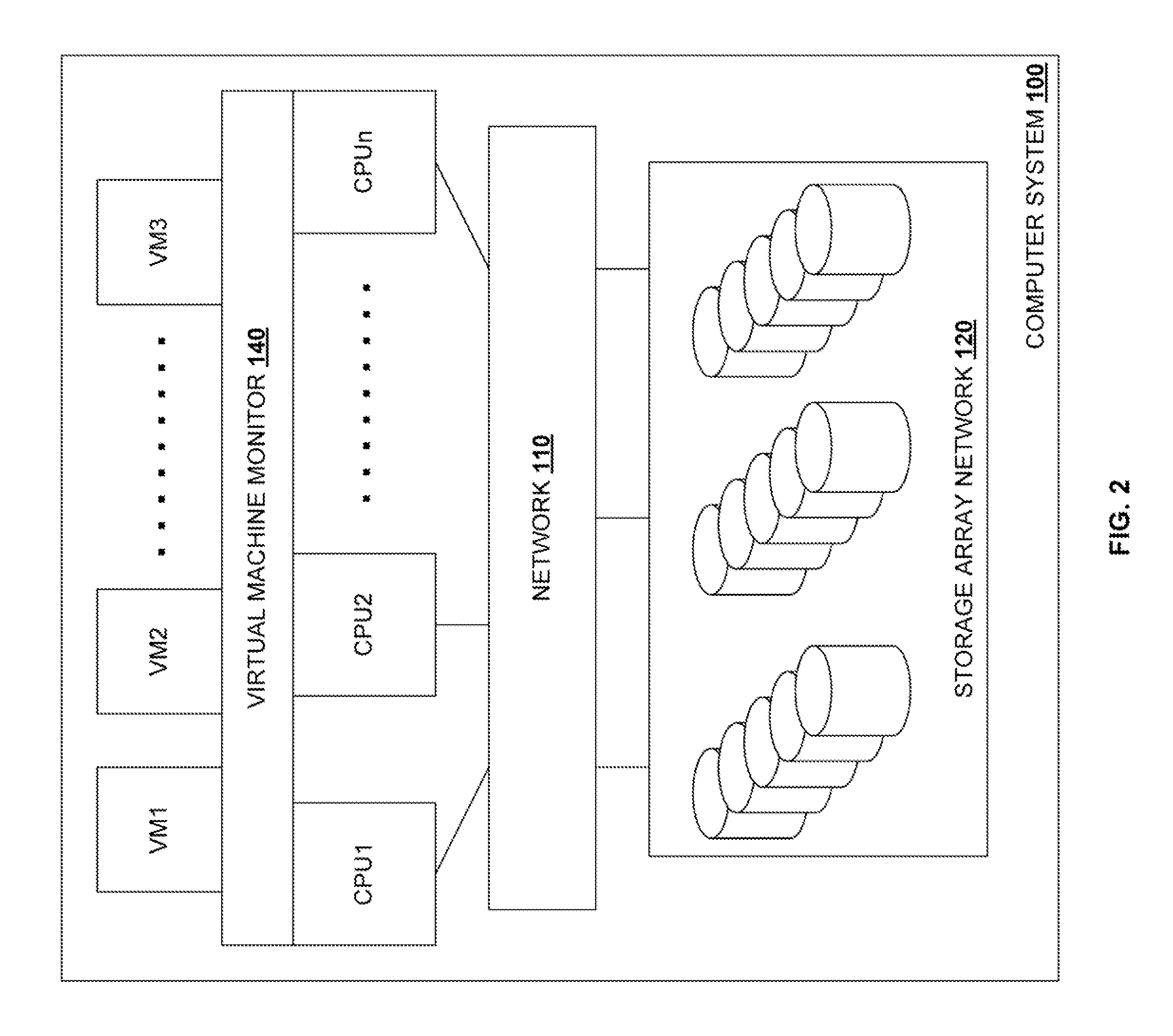
[0050]By way of example, FIG. 1 is a schematic diagram depicting gener...


PUM


Abstract

Systems and methods are provided for determining an optimized placement for a virtual machine in a virtualized environment on the basis of available performance metrics, in which the virtualized environment includes at least two virtual machines, each hosting at least one application, and at least one virtualized hardware system managed by at least one virtualization server.

Description

PRIORITY CLAIM AND CROSS-REFERENCE TO RELATED APPLICATIONS[0001]The present patent application claims the priority benefit of U.S. Provisional Pat. App. 61 / 247,287 filed Sep. 30, 2009.[0002]The present application is a continuation-in-part of U.S. patent application Ser. No. 11 / 773,825 filed Jul. 5, 2007, entitled “Managing Application System Load,” which claims the priority benefit of U.S. Provisional Pat. App. 60 / 806,699 filed Jul. 6, 2006.[0003]Each of the above-listed applications is incorporated herein by reference. Also incorporated herein by reference in their entireties are each of the following:[0004]U.S. patent application Ser. No. 11 / 961,186 filed Dec. 20, 2007, entitled “Methods and Systems for Identifying Application System Storage Resources”, which claims the priority benefit of U.S. Provisional Pat. App. 60 / 871,444 filed Dec. 21, 2006; and[0005]U.S. patent application Ser. No. 12 / 808,043 filed Jun. 14, 2010, entitled “Evaluating And Predicting Computer System Performa...

Claims


Application Information

Patent Timeline
IPC IPC(8): G06F15/173G06F9/455
CPCG06F11/3495G06F9/5088H04L67/1097Y02B60/165Y02B60/162Y02D10/00
Inventor SMIRNOV, GEORGEHU, KENNETHKAELI, DAVID
Owner AKORRI NETWORKS
Learn More