
Circular polarization antenna structure with a dual-layer ceramic and method for manufacturing the same

a circular polarization antenna and ceramic technology, applied in the direction of antenna earthings, waveguide devices, resonance antennas, etc., can solve the problems of low zenith gain unstable conductivity of the circular polarization antenna with single-layer substrate, etc., to achieve good conductivity stability of the circular polarization antenna structure with the dual-layer ceramic, good structure stability of the two ceramic structures, and good conductivity stability

Active Publication Date: 2012-01-10
RRT TECH LTD
View PDF3 Cites 6 Cited by
  • Summary
  • Abstract
  • Description
  • Claims
  • Application Information

AI Technical Summary

Benefits of technology

"The present invention provides a circular polarization antenna structure with a dual-layer ceramic and a method for manufacturing the same. The antenna structure has advantages such as good receiving effect, increased conductivity stability, and high bandwidth, high zenith gain, and good axial ration bandwidth. The manufacturing process involves forming metal layers on a hard dielectric body, calculating the position of an antenna feed pin, and forming a through hole in the hard dielectric body. The two hard dielectric bodies are then adhered together using an adhesive element. The bandwidth of the antenna structure can be adjusted for different usage requirements. The structure stability is good, and the resistivity matching is easily achieved. Overall, the invention provides a reliable and efficient solution for circular polarization antenna applications."

Problems solved by technology

However, the zenith gain of the circular polarization antenna with single-layer substrates is low.
In addition, the copper foil pasted on the on the circular polarization antenna by the foamed plastic is compressed easily by external force, so the conductivity of the circular polarization antenna with single-layer substrates is unstable.

Method used


Image

  • Circular polarization antenna structure with a dual-layer ceramic and method for manufacturing the same
  • Circular polarization antenna structure with a dual-layer ceramic and method for manufacturing the same
  • Circular polarization antenna structure with a dual-layer ceramic and method for manufacturing the same

Examples


Embodiment Construction

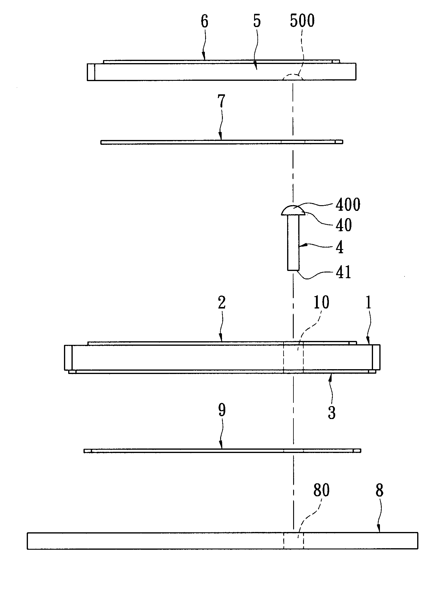
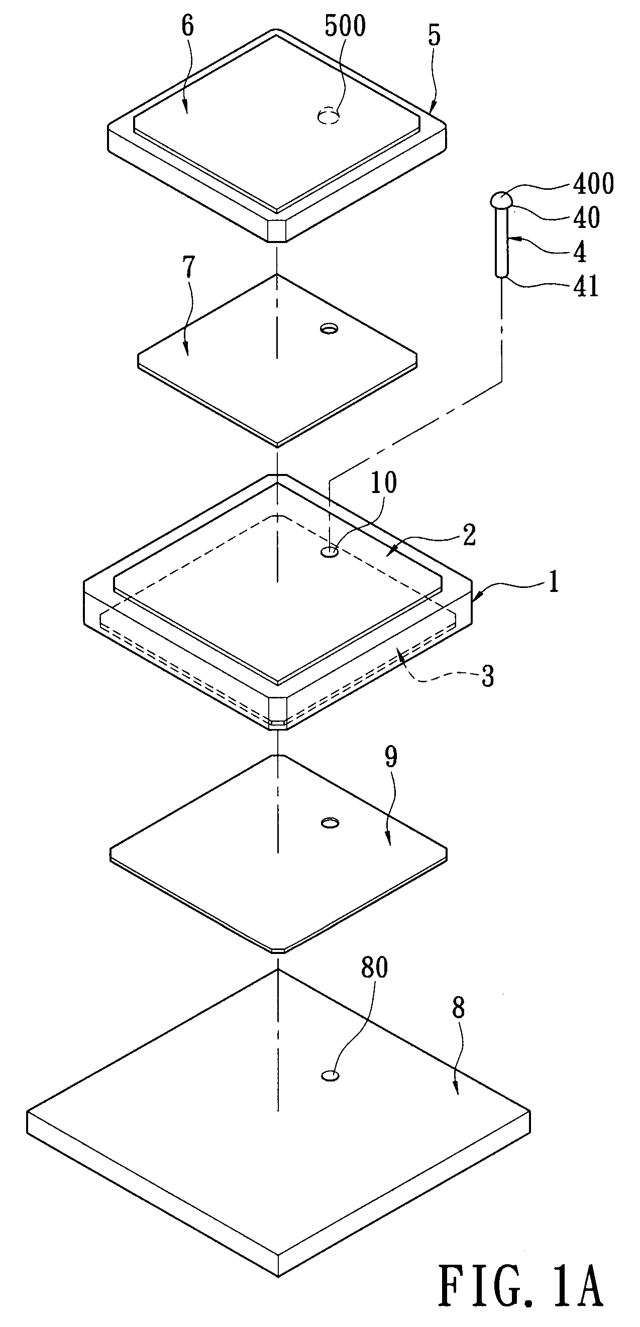
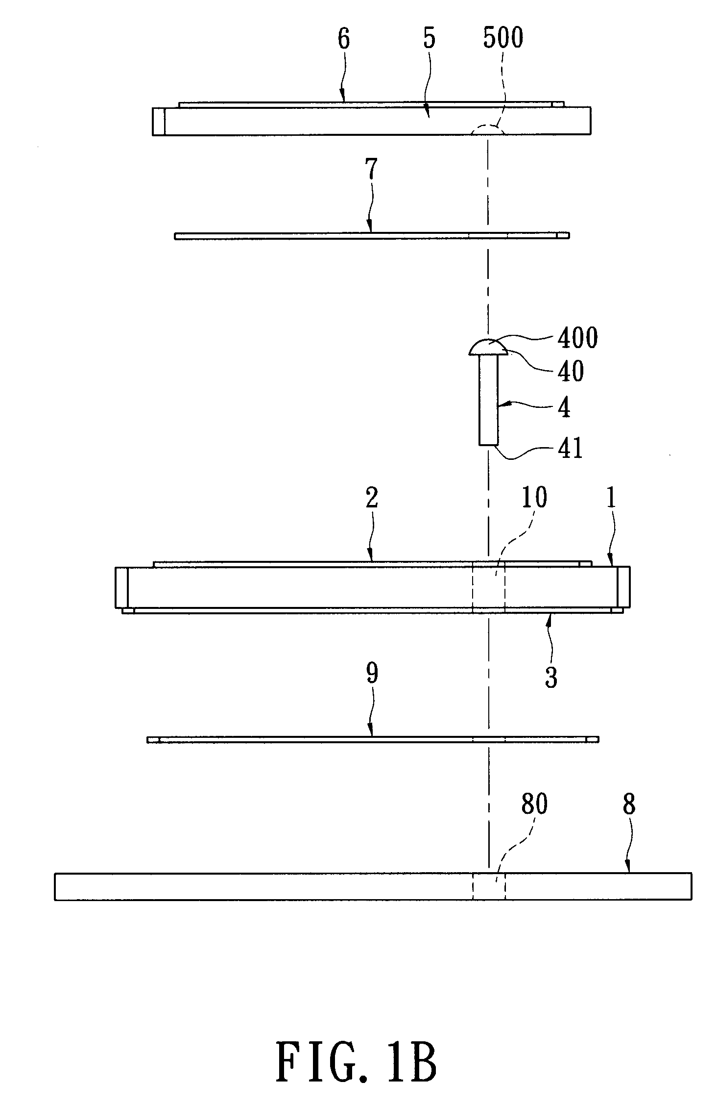
[0022]Referring to FIGS. 1A and 2B, the present invention provides a circular polarization antenna structure with a dual-layer ceramic, including: a first hard dielectric body 1, a first metal layer 2, a grounding layer 3, an antenna feed pin 4, a second hard dielectric body 5, a second metal layer 6 and an adhesive element 7.

[0023]The first hard dielectric body 1 can be made of an insulative material such as ceramic, and the first hard dielectric body 1 has a through hole 10. In addition, the first metal layer 2 is formed on a top surface of the first hard dielectric body 1, and the grounding layer 3 is formed on a bottom surface of the first hard dielectric body 1. However, the feature of the first hard dielectric body 1 being made of ceramic is just an example. Any dielectric material can be applied to the first hard dielectric body 1.

[0024]Moreover, the antenna feed pin 4 passes through the through hole 10 of the first hard dielectric body 1. The top side 40 of the antenna feed ...


PUM

PropertyMeasurementUnit
hardaaaaaaaaaa
receiving frequencyaaaaaaaaaa
frequencyaaaaaaaaaa

Abstract

A circular polarization antenna structure with a dual-layer ceramic includes a first hard dielectric body, a first metal layer, a grounding layer, an antenna feed pin, a second hard dielectric body, a second metal layer and an adhesive element. The first metal layer and the grounding layer dispose on a top surface and a bottom surface of the first hard dielectric body. The antenna feed pin passes through the through hole of the first hard dielectric body, the top side of the antenna feed pin is fixed on the top surface of the first hard dielectric body, and the bottom side of the antenna feed pin extends outwards from the bottom surface of the first hard dielectric body. The second hard dielectric body disposes above the top side of the first hard dielectric body. The second metal layer disposes on the top surface of the second hard dielectric body.

Description

BACKGROUND OF THE INVENTION[0001]1. Field of the Invention[0002]The present invention relates to a circular polarization antenna structure and a method for manufacturing the same, and particularly relates to a circular polarization antenna structure with a dual-layer ceramic and a method for manufacturing the same.[0003]2. Description of Related Art[0004]Due to the development of communication technology, a lot of electronic products have been developed that use wireless communication technology, such as cell phones, wireless Internet devices, and personal digital assistants (PDAs), etc. The requirements demanded by consumers for the wireless communication devices has become higher and higher, namely in terms of the appearance and dimensions of the devices. For cell phones, the receiving frequency has developed from a single frequency, to two, then three, and now four frequencies. Consumers also prefer cell phones having the characteristics of an appealing appearance, small dimensio...

Claims


Application Information

Patent Timeline
Patent Type & Authority Patents(United States)
IPC IPC(8): H01Q1/38
CPCH01Q9/0414H01Q5/378H01Q9/0428Y10T29/49016
Inventor CHENG, TA-FUWANG, HUI-CHIEHTSENG, YUAN-PIAO
Owner RRT TECH LTD
Learn More