
Real-time gain compensation for photo detectors based on energy peak detection

a photo detector and real-time gain technology, applied in the field of nuclear medical imaging, can solve the problems of inability to avoid inability to achieve temperature stabilization and gradient shielding engineering solutions, and inability to achieve localized heating induced by the gradient of mr, etc., to achieve the effect of reducing noise, reducing noise, and reducing nois

Active Publication Date: 2012-01-03
SIEMENS MEDICAL SOLUTIONS USA INC
View PDF1 Cites 5 Cited by
  • Summary
  • Abstract
  • Description
  • Claims
  • Application Information

AI Technical Summary

Benefits of technology

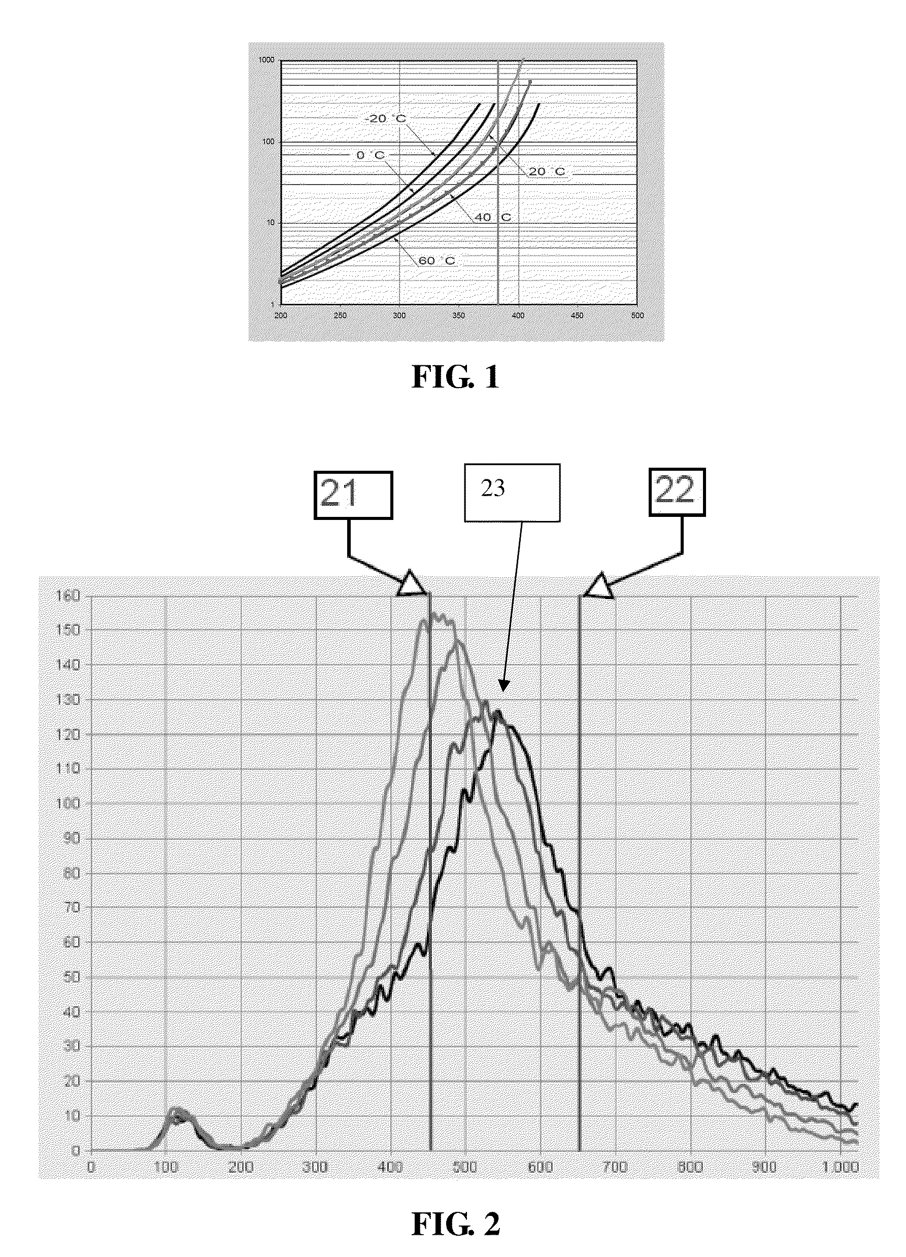
[0010]Accurate determination of the energy peak of coincidence events can be helpful for determining whether an annihilation has occurred. If, as shown in FIG. 2, the peak shifts as a function of a change in temperature, the total integral (equivalent of the number of detected and qualified events) between lower-level discriminator (LLD) 21 and the upper-level discriminator (ULD) 22 may not be as great because the peak is not centered in between the two. Accordingly, some events may be incorrectly categorized as true coincidence or scatter events. Therefore, the system can compensate for the changes in gain because of temperature variation.
[0011]A temperature control system can hold the temperature of the photo detectors at a constant value, but this solution can result in additional cost, engineering noise, and space requirement. Therefore, a more robust, cost-effective, space saving, and low noise solution is needed and embodiments of the present disclosure seek to provide such a solution.
[0012]The present disclosure teaches a method, process, and apparatus for compensating for changes to the gain of photo detectors caused by changes in temperature. The compensation improves identification of scatter, random, true coincidence events. Improved identification can increase the accuracy of a finally rendered image.

Problems solved by technology

However, the gain of APD is sensitive to temperature fluctuation even when the reverse-biasing voltage is constant.
Although the temperature of the APD can be controlled by a detector cooling system, localized heating induced by the gradient of MR cannot be avoided and engineering solutions for temperature stabilization and gradient shielding might be impractical or cost prohibitive.
A temperature control system can hold the temperature of the photo detectors at a constant value, but this solution can result in additional cost, engineering noise, and space requirement.

Method used


Image

  • Real-time gain compensation for photo detectors based on energy peak detection
  • Real-time gain compensation for photo detectors based on energy peak detection
  • Real-time gain compensation for photo detectors based on energy peak detection

Examples


Embodiment Construction

[0023]Preferred embodiments will be described more fully hereinafter with reference to the accompanying drawings. Other embodiments are contemplated in many different forms and this disclosure should not be construed as limited to the embodiments set forth herein; rather, these embodiments are provided so that this disclosure will be thorough and complete, and will fully and clearly convey the scope of the disclosure to those skilled in the art. In the drawings, like numbers refer to like elements.

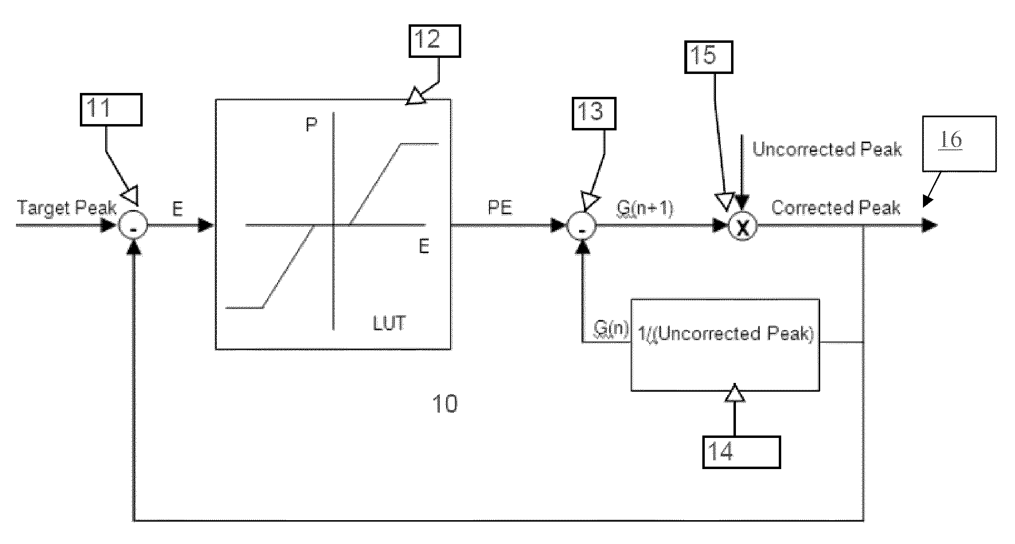
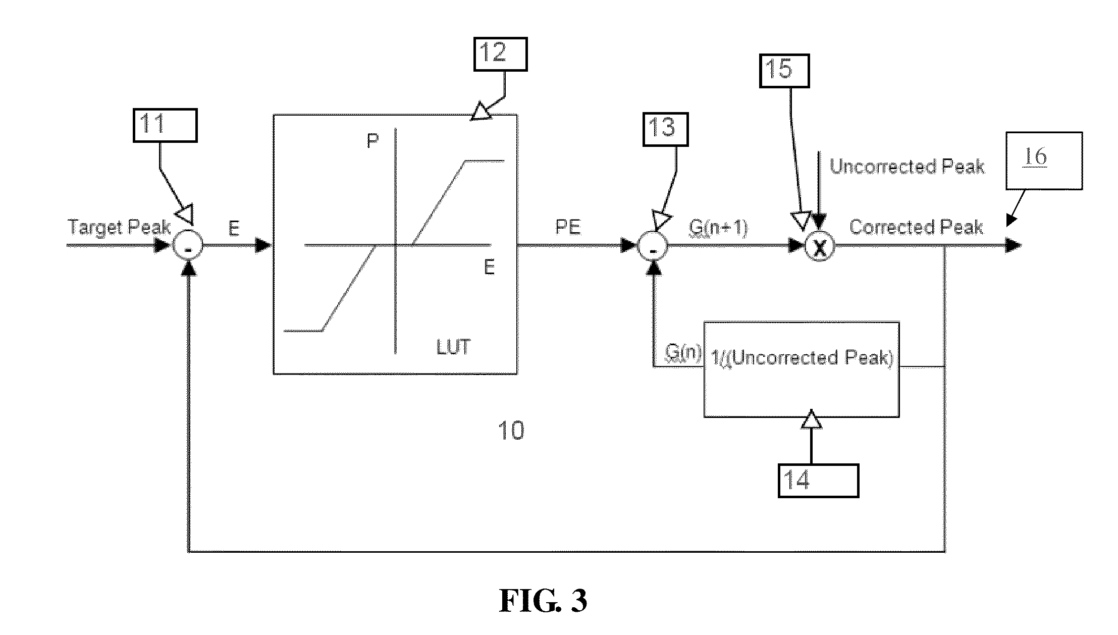
[0024]FIG. 3 illustrates an exemplary embodiment including closed-loop control system 10. In this embodiment, a target energy peak can first be determined to be a constant bin value, for example, bin 128, or may be determined during a calibration process in which 511 keV events can be acquired. The feedback of the control system can be the energy peak position bin measured from energy histogramming for a certain amount of events. The bin corresponding to the detected energy peak is then kn...


PUM


Abstract

A method, process and apparatus for compensating for changes to the gain of photo detectors in a nuclear imaging apparatus is disclosed. Specifically, embodiments detect positron annihilation event pulses using photo detectors. Changes to the gain of the photo detectors are compensated for by determining the relationship of a detected event pulse peak with a target event pulse peak. Based on the difference between these two peaks, a corrected gain is determined in a closed-loop control system. The corrected gain can be used to compensate for temperature changes that can affect the gain of the photo detectors.

Description

CROSS REFERENCE TO RELATED APPLICATIONS[0001]The present application claims priority to U.S. Provisional Patent Application No. 61 / 097,338, filed on Sep. 16, 2008, which is hereby incorporated by reference in its entirety, for all purposes, herein.BACKGROUND OF THE INVENTION[0002]1. Technical Field[0003]In general, the present disclosure relates to nuclear medical imaging. More particularly, the disclosure relates to Positron Emission Tomography (PET) and Single Photon Emission Computed Tomography (SPECT) compensating for changes to the gain of a photo detector due, inter alia, temperature variation.[0004]2. General Background of the Invention[0005]Nuclear medicine is a unique specialty wherein radiation emission is used to acquire images that show the function and physiology of organs, bones or tissues of the body. The technique of acquiring nuclear medicine images entails first introducing radiopharmaceuticals into the body—by either injection or ingestion. These radiopharmaceutic...

Claims


Application Information

Patent Timeline
Patent Type & Authority Patents(United States)
IPC IPC(8): H01L27/00
CPCG01T1/1648
Inventor SCHMAND, MATTHIAS J.HU, DONGMINGBURBAR, ZIAD
Owner SIEMENS MEDICAL SOLUTIONS USA INC
Learn More