
Detector system for detecting glowing particles

a detector system and glowing particle technology, applied in the field of can solve the problems of detectors often failing to react, delay reaction, preventative and protective systems, etc., and achieve the effect of greater precision

Inactive Publication Date: 2004-05-11
FIREFLY AB
View PDF11 Cites 4 Cited by
  • Summary
  • Abstract
  • Description
  • Claims
  • Application Information

AI Technical Summary

Benefits of technology

Another technical problem is one of realising the advantages that are afforded when at least two of the sensor units or sensor sections in the inventive detector arrangement have sensing lobes which cover the cross-section of a loose material transportation path, and to accurately establish the energy content of an indicated single particle on the basis of received signals related to a narrow wavelength range, regardless of the orientation of the particle in said cross-section and while taking the distance from respective detectors into account.
Those advantages that are primarily afforded by an inventive detector arrangement and particularly when said arrangement is included in a preventative and protective system reside in the provision of conditions which enable two or more sensor units or sensor sections to evaluate the high energy content of individual, loose particles passing said sensor units or sensor sections with greater precision than was earlier possible regardless of the position of the particle within a cross-section of its path as a result of sensing such a particle in each of the sensor units or sensor sections simultaneously with mutually discrete and narrow wavelength ranges located within the wavelength spectrum of the total radiation of the particle and by processing the sub-intensity signals generated by said single particle from each of the sensor units or sensor sections so as to enable the relevant energy content of the particle to be established and to cause an activation unit to be brought to an activating mode when said energy content exceeds a predetermined value.

Problems solved by technology

With regard to sensor units included in detector arrangements of the aforesaid kind and similar preventative applications, it has been found that they have a delayed reaction in industrial processes or are not sufficiently sensitive to be considered as an effective damage limiting means, which also applies to the output signal evaluating unit and the activation unit.
It is known to use temperature detectors in the present context, although experiences have shown in practice that these detectors often fail to react until a fire has already developed.
Although flame detectors used in the present context are sensitive to small (low) flames, their use in a preventative, protective system is excluded because they react much too late.
Practical experiences, however, indicate that even discrete particles that radiate solely within one wavelength range, solely for thermal radiation in a transport path, having a temperature in the range of 400.degree. C. are a fire and explosion risk in various process plants where combustible, finely divided and loose material is transported with the aid of a vehicle gas or vehicle gas mixture, preferably an air stream.

Method used


Image

  • Detector system for detecting glowing particles
  • Detector system for detecting glowing particles
  • Detector system for detecting glowing particles

Examples


first embodiment

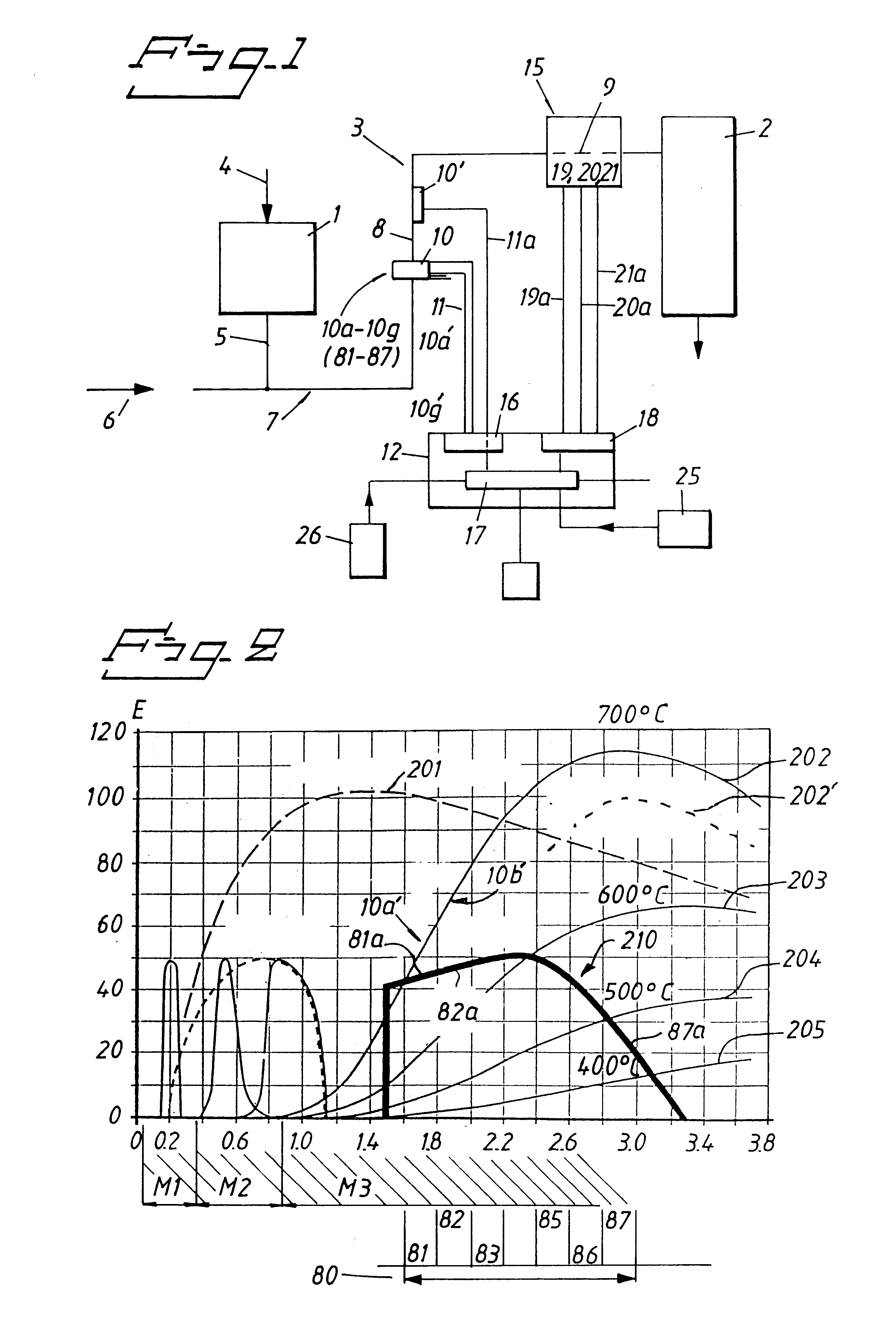
In a first embodiment, it is required that all output signals 10a'-10g' from the sensor sections 10a to 10g shall be higher than those significant to the stored values 81a-81g corresponding to the graph 210, in order for the calculating circuit 17 to send a signal to the circuit 18.

second embodiment

In a second embodiment, it may be required that a chosen predetermined number of output signals whose respective sub-intensities exceed said maximised value are at least required for causing the calculating circuit 17 to send a signal to the circuit 18.

FIG. 7 is intended to indicate by way of example that the sensor sections 10a, 10c, 10d and 10e alone shall indicate, via their output signals 10a', 10b'. . . 10g', an excessively high, relative energy content for actuation of the circuit 18 via a calculating circuit 17 included in a function block 17.

The signal 10a' is compared with the value 81a in a comparison circuit 71, and a signal indicating an excessively high value is sent on line 71a when the value of the signal exceeds the stored value.

The comparison circuit 71 may be modified so that the signal transmitted on the line 71a will correspond to the evaluated difference value.

In this latter application, it may be convenient to evaluate the magnitude of the difference values, su...


PUM


Abstract

The present invention relates to a detector arrangement inlcuded in a preventative, protective system. The sensor lobes of at least two sensor units or sensor sections are arranged to cover the cross-sectional area of a tubular transport device. The arrangement includes a unit for evaluating the output signals of the sensor units, and an activation unit which is adapted to evaluate sensed sub-intensities relating to wavelength ranges and each deriving from said sensor units and to thus coordinate received wavelength-related and sub-intensity-dependent signals for calculating and establishing therefrom the relevant disposition of the particle to initiate fire and / or explosion or some other danger.

Description

The present invention relates generally to a detector arrangement and more specifically to a detector arrangement which is designed to detect in a stream of loose material the presence of one or more individual particles that has / have a temperature and / or an energy content such as to be able to incite fire or cause an explosion to take place in a downstream particle or material collecting risk zone.By loose material is meant any type of material that can be transported by or in a gas mixture, normally air, wherewith the individual particles of the loose material are normally spaced from one another.Loose material of this kind may consist of very fine particles in the nature of dust, or may consist of powder particles or granular particles. Wood chips, pellets, straw and like materials can also be transported in this way.The inventive detector arrangement is adapted to be included in a preventative, protective system that includes one or more sensor units, an evaluation unit evaluati...

Claims


Application Information

Patent Timeline
IPC IPC(8): G01J5/60
CPCG01J5/602
Inventor JANSSON, LENNART CARL ERIK
Owner FIREFLY AB
Learn More