Method of manufacturing semiconductor device
a manufacturing method and semiconductor technology, applied in semiconductor devices, semiconductor/solid-state device details, electrical devices, etc., can solve the problems of unavoidable loss or thinning of cap film 8 during etching, and achieve the effects of high yield, reduced capacity, and increased reliability
- Summary
- Abstract
- Description
- Claims
- Application Information
AI Technical Summary
Benefits of technology
Problems solved by technology
Method used
Image
Examples
first embodiment
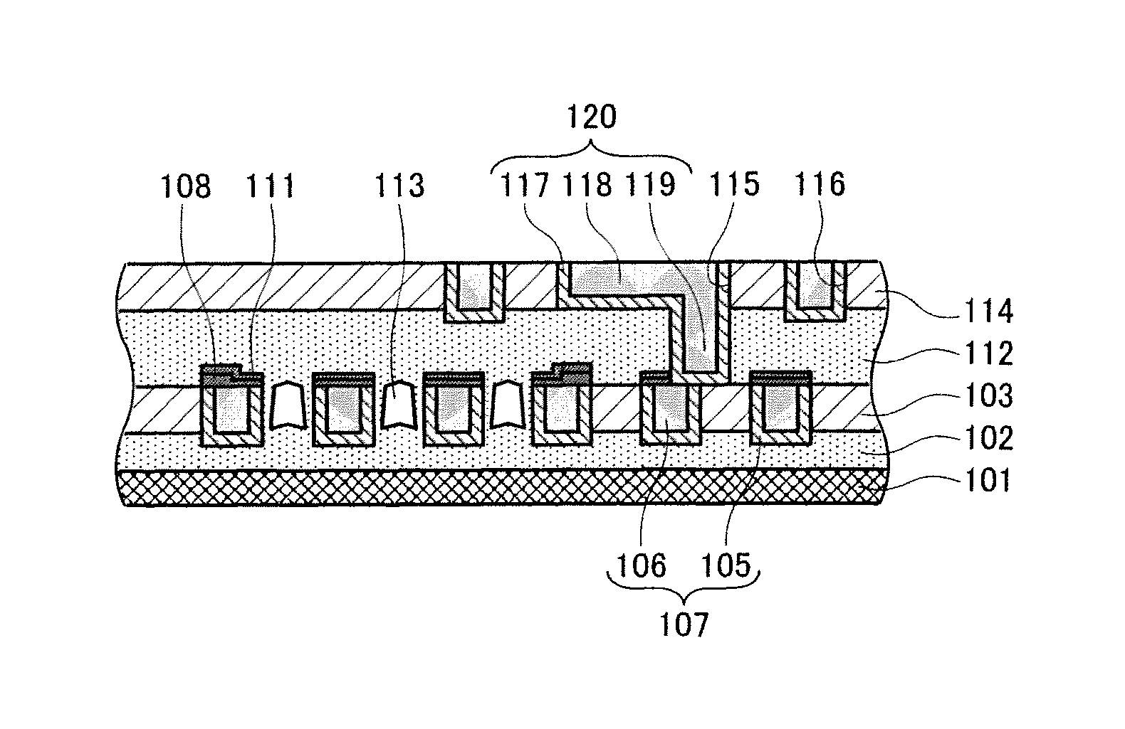
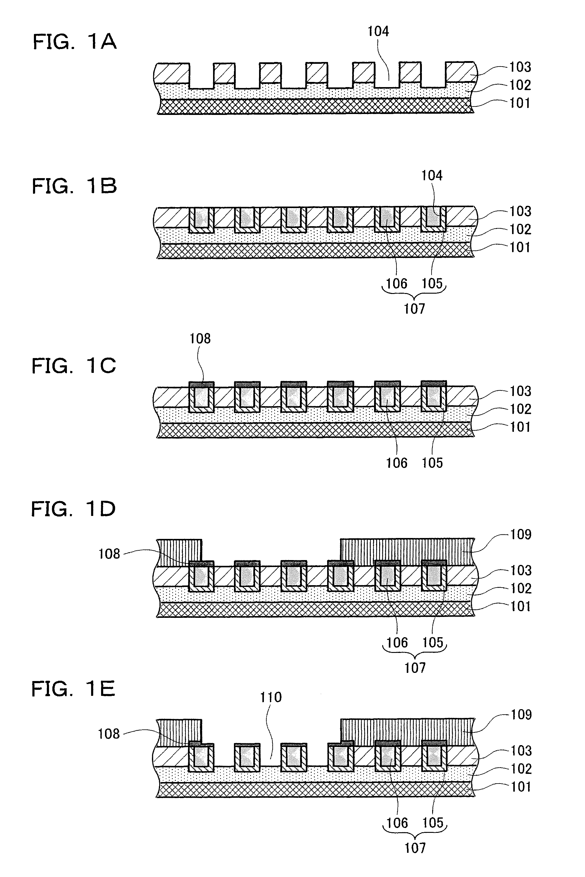
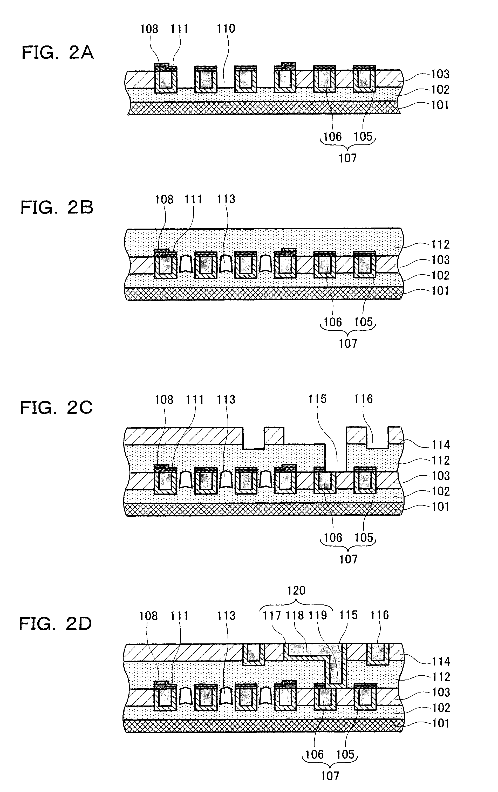
[0116]A first embodiment of the present invention will be described below with reference to FIGS. 1A, 1B, 1C, 1D, 1E, 2A, 2B, 2C, 2D, 3A, 3B, and 3C. FIGS. 1A, 1B, 1C, 1D, 1E, 2A, 2B, 2C, and 2D are sectional views illustrating steps of a method of manufacturing a semiconductor device according to the first embodiment. FIGS. 3A, 3B, and 3C are sectional views illustrating steps of the method of manufacturing the semiconductor device in which a second cap film is formed before a resist pattern is removed according to the first embodiment.
[0117]First, as shown in FIG. 1A, an interlayer insulating film 102 and an inter-wire insulating film 103 are deposited on a surface of a semiconductor substrate 101. Wiring grooves 104 are then formed in an upper part of a film stack of the interlayer insulating film 102 and the inter-wire insulating film 103 by photolithography and dry etching. In the present embodiment, an SiOC film is used as the interlayer insulating film 102, and an SiO2 film i...
second embodiment
[0151]A second embodiment of the present invention will be described below with reference to FIGS. 4A, 4B, 4C, 4D, 4E, 5A, 5B, 5C, 5D, 6A, 6B, and 6C. Only the differences of the present embodiment from the first embodiment will be described. The description of parts similar to those in the first embodiment is omitted.
[0152]FIGS. 4A, 4B, 4C, 4D, 4E, 5A, 5B, 5C, and 5D are sectional views illustrating steps of a method of manufacturing a semiconductor device according to the second embodiment. FIGS. 6A, 6B, and 6C are sectional views illustrating steps of the method of manufacturing the semiconductor device in which a second cap film is formed before a resist pattern is removed according to the second embodiment.
[0153]The present embodiment is different from the first embodiment in that a first cap film 108 has a fixed thickness of 10 nm in FIG. 5A. Thus, in FIG. 4E, when gaps 110 are each formed between lower wires 107, the first cap film 108 in an air gap forming area, which is not...
third embodiment
[0172]A third embodiment of the present invention will be described below with reference to FIGS. 7A, 7B, 7C, 7D, 7E, 8A, 8B, 8C, 8D, 9A, 9B, and 9C. Only the differences of the present embodiment from the first embodiment will be described. The description of parts similar to those in the first embodiment is omitted.
[0173]FIGS. 7A, 7B, 7C, 7D, 7E, 8A, 8B, 8C, 8D, 9A, 9B, and 9C are sectional views illustrating steps of a method of manufacturing a semiconductor device according to the third embodiment.
[0174]The present embodiment is different from the first embodiment in that a liner film 121 is deposited on surfaces of an inter-wire insulating film 103 and a first cap film 108 as shown in FIG. 7D.
[0175]First, as shown in FIG. 7A, an interlayer insulating film 102 and the inter-wire insulating film 103 are deposited on a surface of a semiconductor substrate 101. Wiring grooves 104 are then formed inside the layer stack of the interlayer insulating film 102 and the inter-wire insulat...
PUM
 Abstract
Description
Claims
Application Information
 - R&D
- Intellectual Property
- Life Sciences
- Materials
- Tech Scout
- Unparalleled Data Quality
- Higher Quality Content
- 60% Fewer Hallucinations
Browse by: Latest US Patents, China's latest patents, Technical Efficacy Thesaurus, Application Domain, Technology Topic, Popular Technical Reports.
© 2025 PatSnap. All rights reserved.Legal|Privacy policy|Modern Slavery Act Transparency Statement|Sitemap|About US| Contact US: help@patsnap.com


