
Slurry for slicing silicon ingot and method for slicing silicon ingot using the same

a technology of silicon ingot and slurry, which is applied in the direction of manufacturing tools, other chemical processes, chemistry apparatus and processes, etc., can solve the problems of increasing the damage rate of the wafer in the transporting and processing steps of the wafer, increasing the amount of expensive wires, and reducing the thickness of the wafer, so as to reduce the kerf loss and slicing damage, the effect of removing the power of silicon

Inactive Publication Date: 2011-12-13
MITSUBISHI ELECTRIC CORP
View PDF7 Cites 12 Cited by
  • Summary
  • Abstract
  • Description
  • Claims
  • Application Information

AI Technical Summary

Benefits of technology

The present invention relates to a slurry used in slicing silicon ingots for producing solar cells. The technical effect of the invention is to decrease the kerf loss and thickness of wafers, improve the yield of wafers, and reduce the cost of materials for producing wafers. The invention also addresses the problem of uneven thickness and surface irregularities in the wafers caused by the slicing process. Additionally, the invention proposes a method for removing the damaged layer on the surface of the wafers to improve the quality of the wafers.

Problems solved by technology

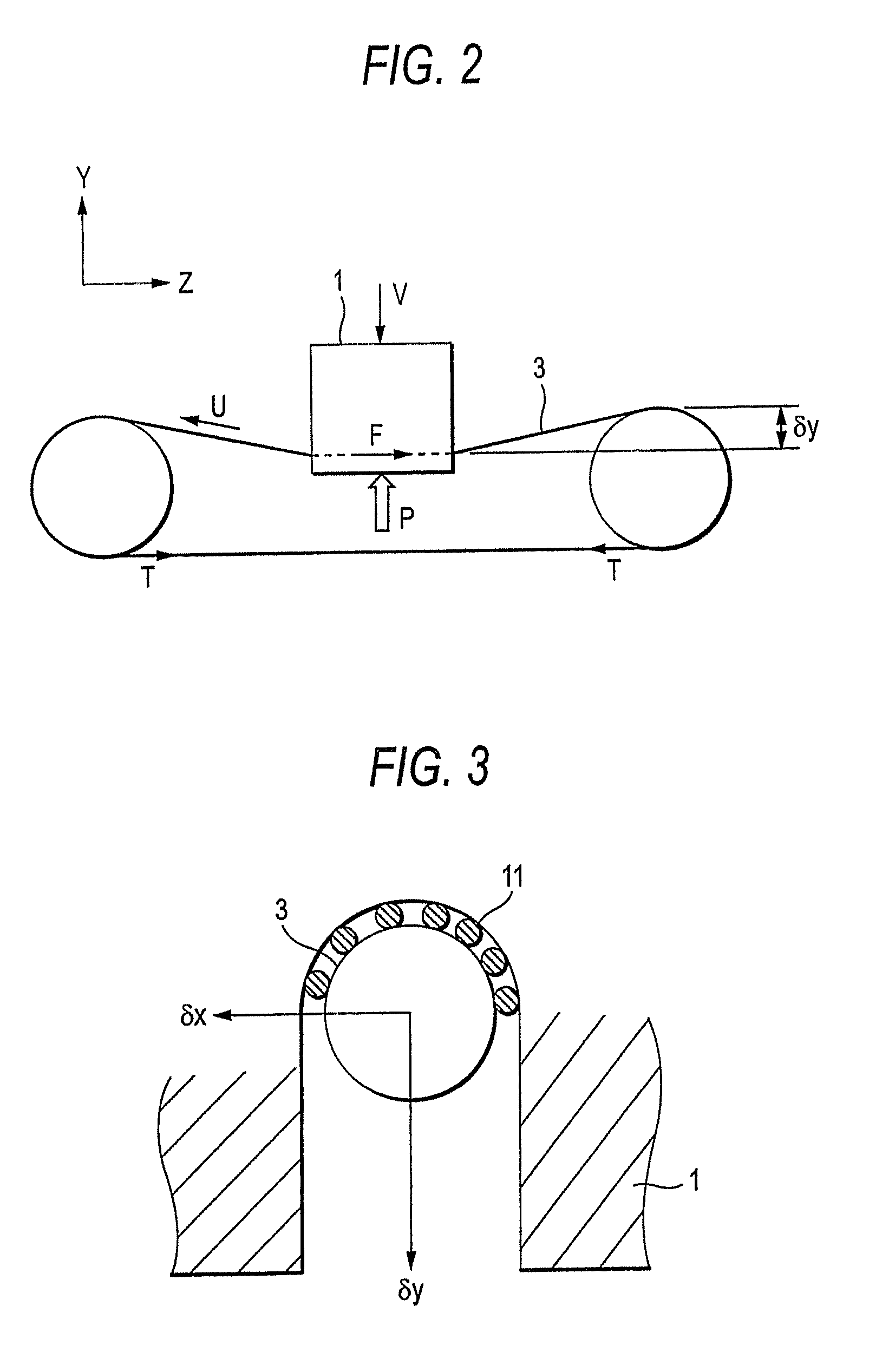
In the case where the running speed U of the wire is increased, the consumption amount of the expensive wire is increased to increase the running cost for slicing.
In the case where the wafer thickness becomes smaller, the damage rate of the wafers in the transporting and processing steps of the wafers is increased.
The depth of the damaged layer is about 10 μm in the conventional techniques, which impairs reduction in thickness of the wafers.

Method used


Image

  • Slurry for slicing silicon ingot and method for slicing silicon ingot using the same
  • Slurry for slicing silicon ingot and method for slicing silicon ingot using the same
  • Slurry for slicing silicon ingot and method for slicing silicon ingot using the same

Examples


embodiment 1

[0042]Upon slicing a silicon ingot with a multi-wire saw, it is necessary to supply abrasive powder continuously to the slicing interface in a suitable amount. A wire is used as means for conveying the abrasive powder to the slicing interface, and a liquid is necessarily used as a medium for dispersing and carrying the abrasive powder on the wire and for reducing the frictional force among the wire, the abrasive powder and the ingot and effecting cooling at the slicing interface. It is necessary to manage the viscosity of the liquid within a certain range. In the case where the viscosity is low, the necessary amount of the abrasive powder cannot be carried on the wire, and in the case where the viscosity is high, on the other hand, the liquid cannot permeate to the slicing interface, and thus the necessary amount of the abrasive powder cannot be supplied to the slicing interface similarly. Furthermore, the liquid pressure at the slicing part is increased to cause a force separating ...

example 1

[0067]A mixed liquid of 40% by mass of glycerin, 56% by mass of water and 4% by mass of sodium hydroxide was produced, to which the same amount of abrasive powder were then added, and the mixture was agitated.

embodiment 2

[0085]The second slurry for slicing a silicon ingot of the invention can considerably decrease unevenness in thickness of wafers for solar cells by adding a small amount of a nonionic polymer surfactant to the slurry described in Embodiment 1. As having been described, upon forming a slicing groove with a wire proceeding in the slicing direction, the slurry is continuously supplied to the slicing groove, whereby dissolution of the wafer in the direction perpendicular to the slicing direction (the thickness direction of the wafer) proceeds by the etching action in the slicing initiation part as compared to the slicing termination part of the ingot. As a result of investigations of various kinds of surfactant in order to prevent the dissolution in the part where the slicing operation is completed without decrease in chemical action at the slicing interface, it has been found that the dissolution in the part where the slicing operation is completed can be largely suppressed through red...


PUM

PropertyMeasurementUnit
average particle diameteraaaaaaaaaa
lengthaaaaaaaaaa
diameteraaaaaaaaaa

Abstract

The invention is a slurry for slicing a silicon ingot, containing a basic material, such as an alkali metal hydroxide, abrasive powder and water, in which the slurry contains the basic material in an amount of from 2 to 6% by mass and glycerin in an amount of from 25 to 55% by mass, based on a total mass of components of the slurry excluding the abrasive powder.

Description

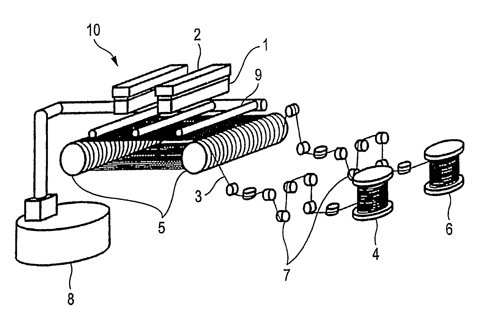
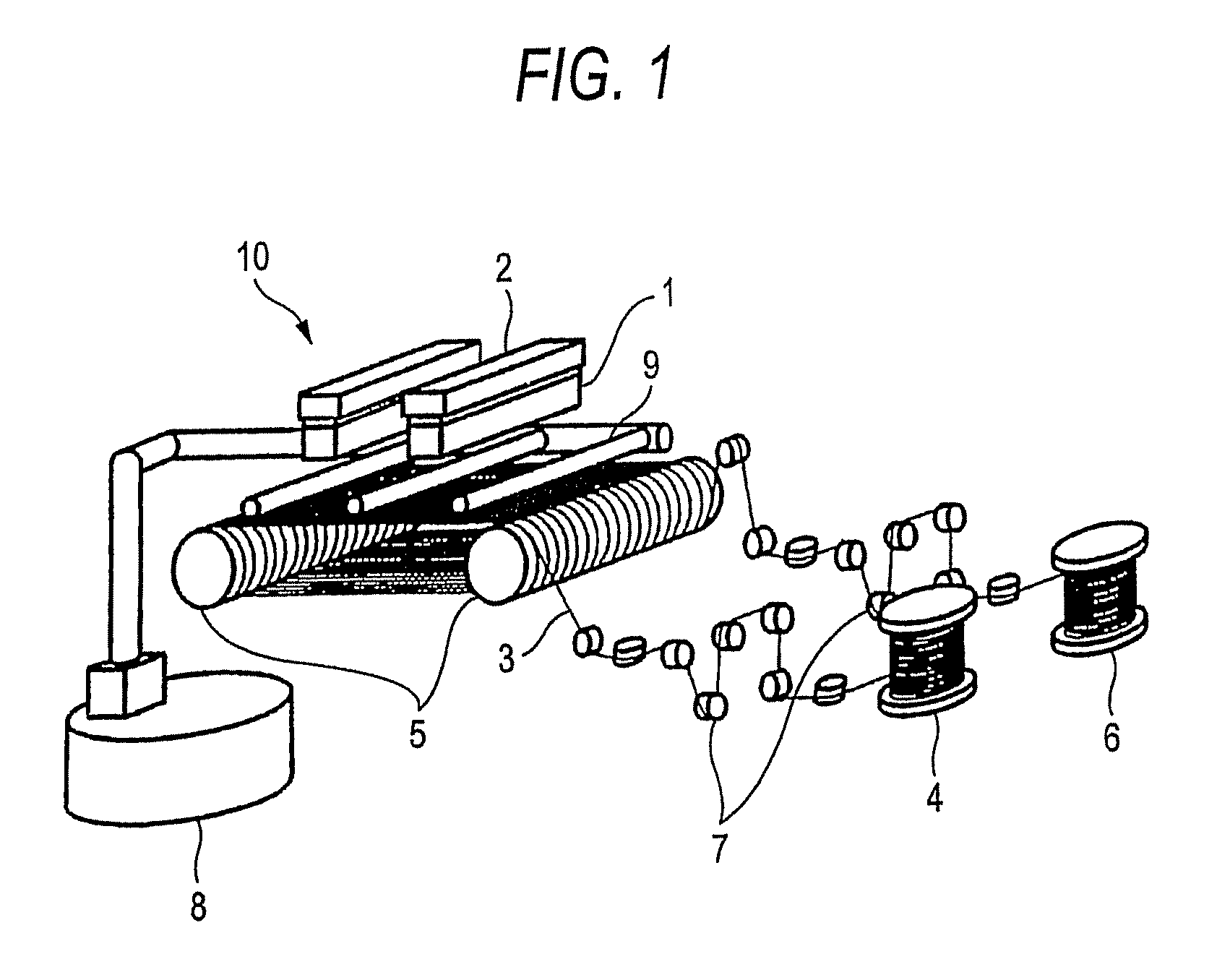
TECHNICAL FIELD[0001]The present invention relates to a slurry used upon slicing a silicon ingot, for example, for producing a wafer for a solar cell, and a method for slicing a silicon ingot using the same.BACKGROUND ART[0002]For slicing a silicon ingot, conventionally, a multi-wire saw has been used that is capable of slicing a large number of wafers at a time with a relatively small kerf loss. FIG. 1 shows a device constitution of a basic multi-wire saw for slicing a silicon ingot for producing a wafer for a solar cell. In a multi-wire saw 10 shown in the figure, numeral 1 denotes a silicon ingot, which is fixed by adhesion to a working plate 2, and in general, a material having a cross section of about 150 mm square and a length of about 400 mm is relatively frequently used.[0003]Numeral 3 denotes a wire fed from a wire feeding mechanism 4, which is wound and suspended on two wire guide rollers 5 at a pitch of about from 0.3 to 0.4 mm and then wound up by a wire winding mechanis...

Claims


Application Information

Patent Timeline
Patent Type & Authority Patents(United States)
IPC IPC(8): B24D3/02C09C1/68C09K3/14
CPCB28D5/007B28D5/045C09K3/1463Y02P70/10C09G1/02C09K3/1409
Inventor KAWASAKI, TAKAFUMIMIMURA, SEIICHINISHIDA, HIROKAZUYOSHIDA, YASUHIRO
Owner MITSUBISHI ELECTRIC CORP
Learn More