
Reduction of greenhouse gas emission from petroleum refineries

a technology of petroleum refinery and greenhouse gas emission, which is applied in the direction of climate sustainability, chemistry apparatus and processes, and petrochemical industries, etc., can solve the problems of high capital investment and operating costs primarily related to air separation plants, uneconomical practicability, and high capital investment and operating costs . the effect of reducing the carbon dioxide emissions of the plan

Inactive Publication Date: 2011-11-15
INST FR DU PETROLE
View PDF10 Cites 11 Cited by
  • Summary
  • Abstract
  • Description
  • Claims
  • Application Information

AI Technical Summary

Benefits of technology

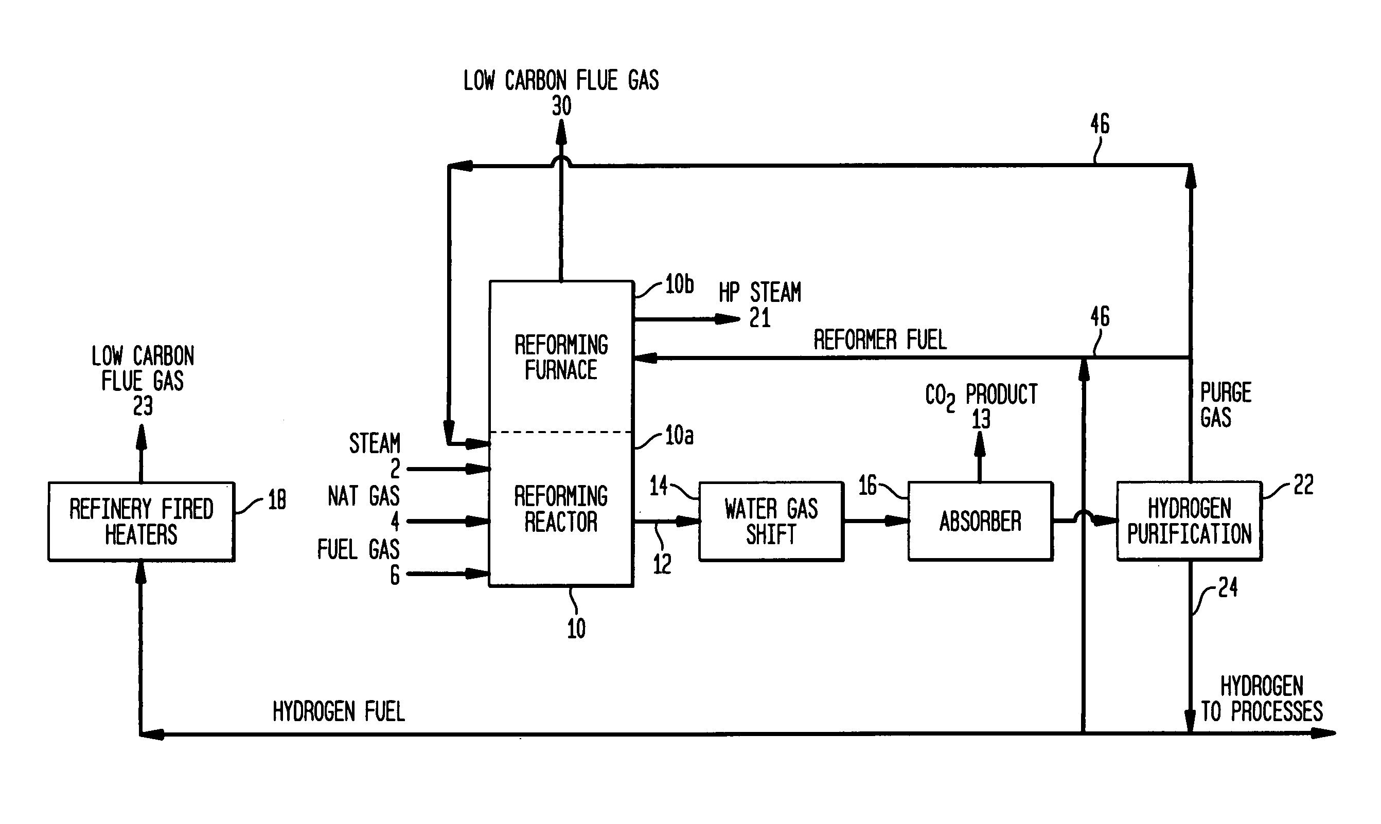
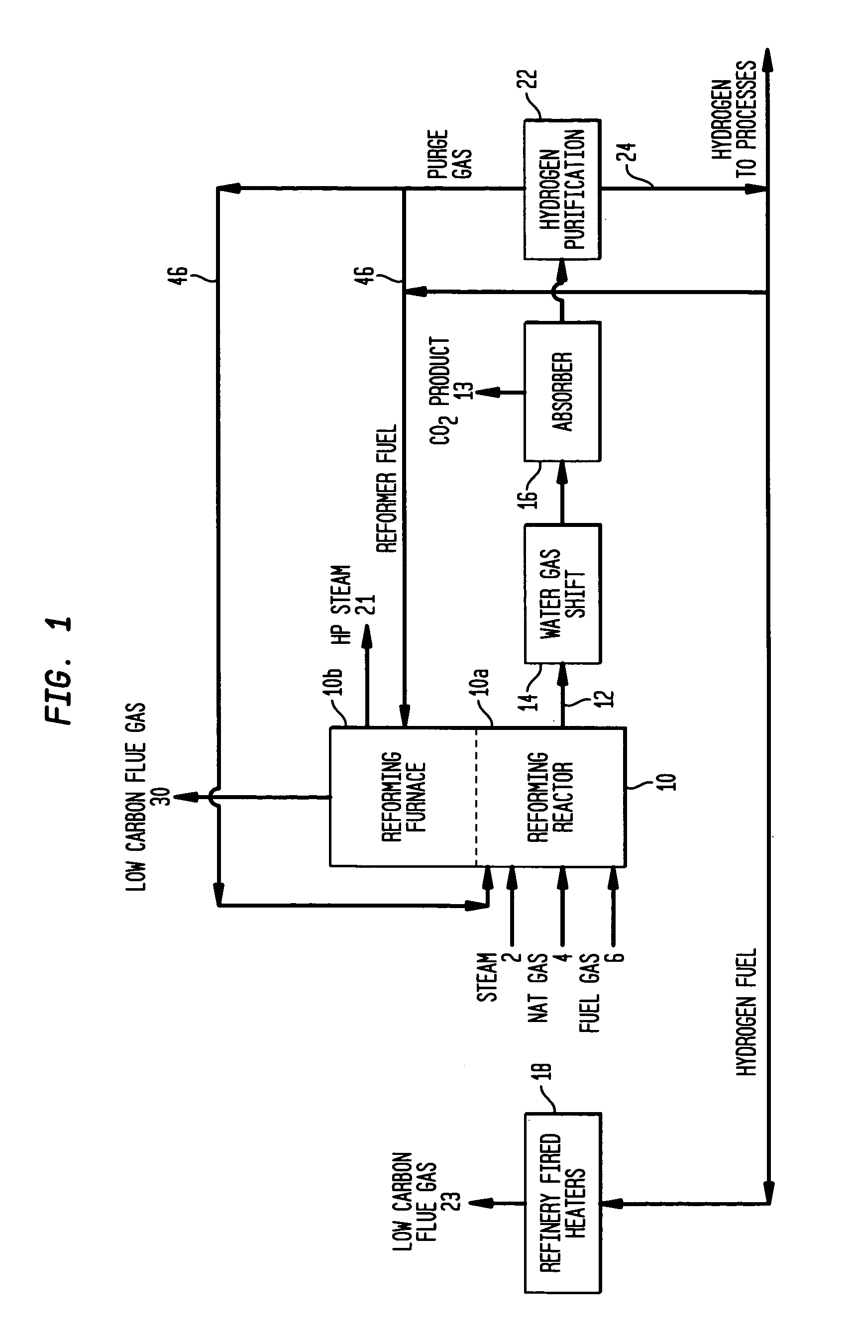
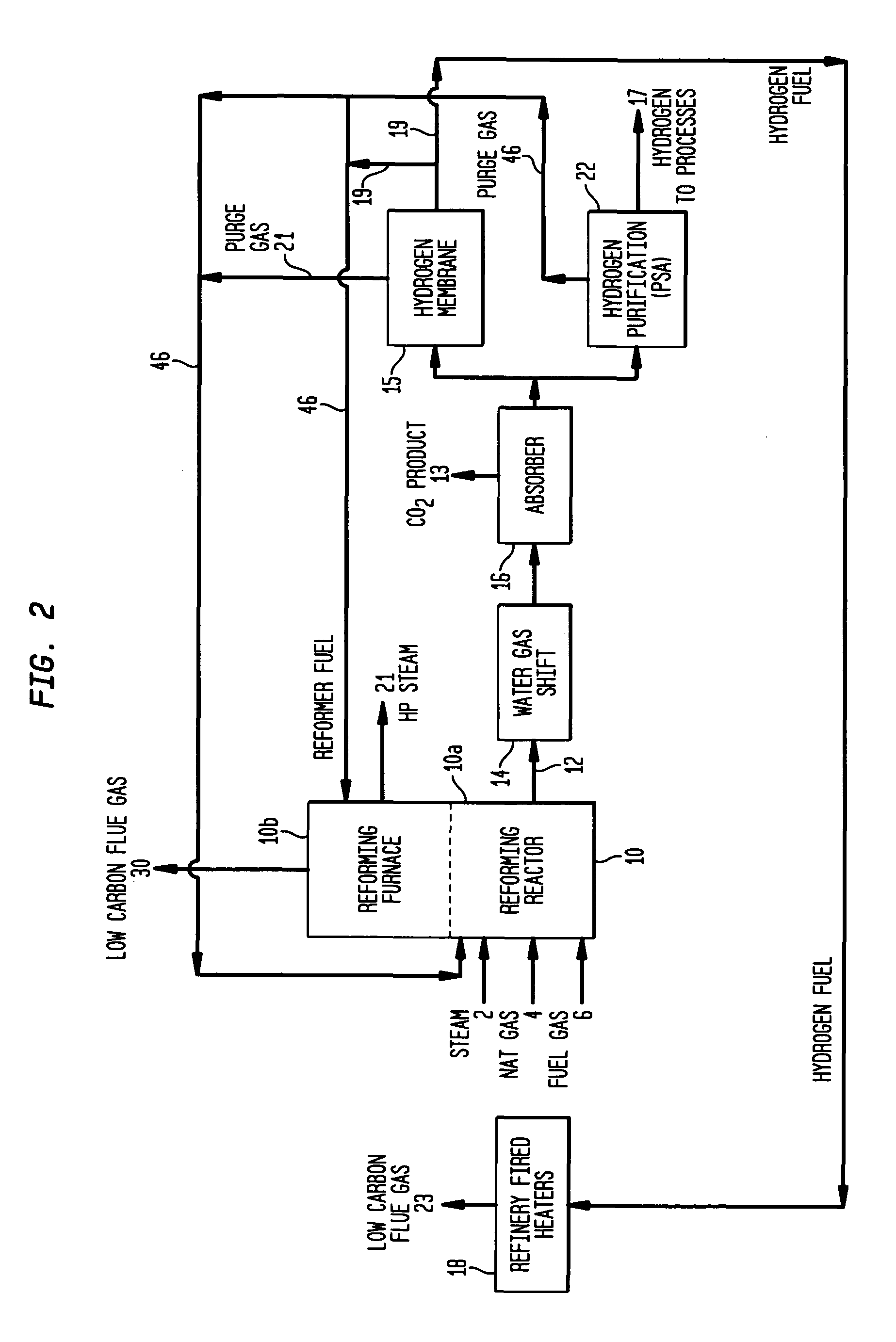
The invention described in this patent reduces carbon dioxide emissions from a petroleum refinery or hydrogen plant by using a low carbon hydrogen stream to fuel process heaters and capture carbon dioxide before it is released. The captured carbon dioxide can be sequestered or utilized for enhanced oil recovery. The process involves a steam reformer, water gas shift, carbon dioxide absorption, and purification steps to create a high purity hydrogen fuel. The carbon emissions of the refinery are reduced by more than 20% and can be as high as (50% or -80%) depending on the refinery's specifications.

Problems solved by technology

Although technology exists for capturing the dilute CO2 from this stream, it is highly capital intensive and not practiced commercially.
However, this configuration also requires a recycle of CO2 to the furnace to moderate the resulting temperature and also results in high investment and operating costs primarily related to the air separation plant and is not economically practical.

Method used


Image

  • Reduction of greenhouse gas emission from petroleum refineries
  • Reduction of greenhouse gas emission from petroleum refineries
  • Reduction of greenhouse gas emission from petroleum refineries

Examples


example

[0042]The following example cases are based upon a typical North American refinery which is currently operated without CO2 capture. The refinery processes 100,000 BPSD of crude with gasoline and diesel being the primary products and other environmentally acceptable liquids also produced. The refinery includes crude atmospheric and vacuum distillation, an FCC Unit, catalytic reforming unit, hydrotreater units, and a natural gas fed SMR Unit.

[0043]The base case with no CO2 capture is outlined in Table 1 and also includes estimated CO2 emissions as reported in the literature. The total CO2 emissions are 115 Lb / Bbl of refinery feed and result in 5,750 STPD of CO2 being emitted to the atmosphere. The SMR unit is fed with natural gas and provides 30.5 mM SCFD of hydrogen. The CO2 emissions are segregated into three sources: from the SMR Unit (862 STPD), from the FCC Unit (1,000 STPD) and from the plant fired heaters (3,888 STPD). It is assumed that the CO2 emissions from the FCC regenerat...


PUM

PropertyMeasurementUnit
temperaturesaaaaaaaaaa

Abstract

The invention described herein relates to a novel process that eliminates the need for post combustion CO2 capture from fired heaters (at atmospheric pressure and in dilute phase) in a petroleum refinery to achieve environmental targets by capturing CO2 in a centralized facility and providing fuel gas low in carbon to the fired heaters. It combines the pre-combustion capture of carbon dioxide with production of a hydrogen fuel source within a refinery to drastically reduce the carbon dioxide emissions of the plant. The hydrogen fuel is utilized for the process fired heaters and the fuel quality (carbon content) can be set to meet the refinery's emissions objectives. Moreover, the carbon dioxide captured can be sequestered and / or utilized for enhanced oil recovery (EOR).

Description

FIELD OF THE INVENTION[0001]Climate change concerns have increased awareness over the level of carbon dioxide (CO2) emissions from various refinery processes. Applicants disclose an efficient and effective technique for reducing the carbon dioxide emissions from a petroleum refinery by capturing the carbon dioxide in a centralized facility and providing fuel gas low in carbon to process fired heaters, which accounts for a high percentage of carbon emissions at a typical refinery facility.BACKGROUND OF THE INVENTION[0002]Process fired heaters are collectively the major source of refinery carbon dioxide emissions. In a typical U.S. refinery, for example, approximately seventy percent (70%) of the carbon dioxide emitted to the atmosphere originates from process fired heaters.[0003]These fired heaters combust natural gas, refinery fuel gas or liquid fuel oil with air and as a result emit a flue gas which is relatively dilute (15 V % or less) in CO2 with nitrogen present as the primary g...

Claims


Application Information

Patent Timeline
Patent Type & Authority Patents(United States)
IPC IPC(8): C01B31/20C01B3/24C01B3/26C01B32/50
CPCC01B3/384C01B3/48C01B2203/0233C01B2203/0283C01B2203/0405C01B2203/0415C01B2203/043C01B2203/0475C01B2203/06C01B2203/0811C01B2203/0827C01B2203/1241C01B2203/145C01B2203/146C01B2203/148Y02P30/00
Inventor MACARTHUR, JAMES B.COLYAR, JAMES J.
Owner INST FR DU PETROLE
Learn More