
Adaptive complex gain predistorter for a transmitter

a complex gain and transmitter technology, applied in the field of adaptive cartesian transmitter linearization and a wireless transmitter, can solve the problems of large and expensive, and inability to cost effectively add features and reduce footprint. the effect of power consumption

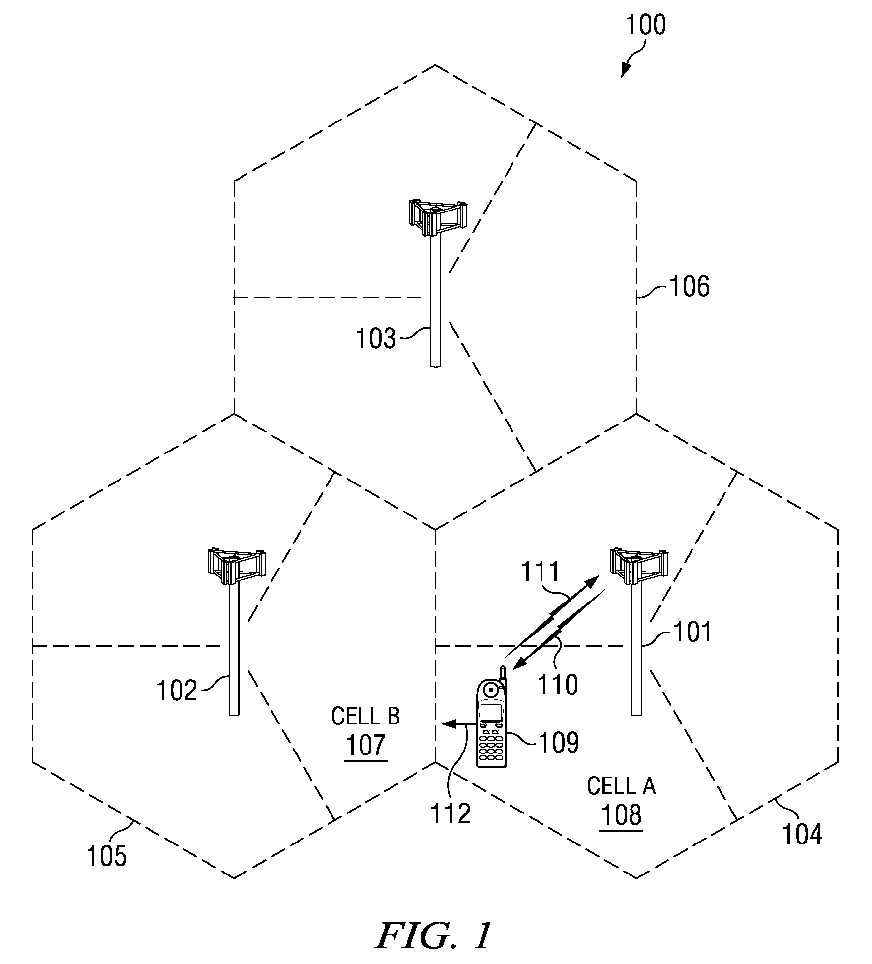
Active Publication Date: 2011-11-08
TEXAS INSTR INC
View PDF3 Cites 20 Cited by
  • Summary
  • Abstract
  • Description
  • Claims
  • Application Information

AI Technical Summary

Benefits of technology

The adaptive predistortion technique effectively reduces distortion and spectral degradation, maintaining signal quality across varying conditions, and is suitable for low-cost, battery-powered wireless transmitters, improving error vector magnitude and adjacent channel leakage ratio performance.

Problems solved by technology

However, for analog / RF designs, the immaturity of advanced processes comes with design challenges that may outweigh the intended advantage.
In a typical handset, 30 to 40% of handset board space is occupied by analog / RF functionality which cannot be re-designed or migrated to the newer process / technology nodes easily, inhibiting vendor ability to cost effectively add features and reduce footprint.
Unfortunately, highly linear amplifiers use relatively large amounts of power and numbers of highly accurate and tightly matched components, making them relatively power consumptive, large and expensive.
Though they perform the best, they are thus disfavored in many wireless applications, particularly those that require low-cost transmitters or transmitters that are subject to large operating voltage excursions.
Though the amplifier then distorts the signal as it amplifies it, the predistortion and the amplifier distortion essentially cancel one another, resulting in an amplified output signal having substantially reduced distortion.
Unfortunately, a factory-calibrated predistortion LUT often fails to linearize the amplifier(s) adequately under varying operational conditions (e.g., temperature, voltage, frequency and voltage standing-wave ratio, or VSWR).

Method used


Image

  • Adaptive complex gain predistorter for a transmitter
  • Adaptive complex gain predistorter for a transmitter
  • Adaptive complex gain predistorter for a transmitter

Examples


system embodiment

[0103]FIG. 12 is a block diagram of mobile cellular phone 1000 for use in the network of FIG. 1. Digital baseband (DBB) unit 1002 can include a digital processing processor system (DSP) that includes embedded memory and security features. Stimulus Processing (SP) unit 1004 receives a voice data stream from handset microphone 1013a and sends a voice data stream to handset mono speaker 1013b. SP unit 1004 also receives a voice data stream from microphone 1014a and sends a voice data stream to mono headset 1014b. Usually, SP and DBB are separate ICs. In most embodiments, SP does not embed a programmable processor core, but performs processing based on configuration of audio paths, filters, gains, etc being setup by software running on the DBB. In an alternate embodiment, SP processing is performed on the same processor that performs DBB processing. In another embodiment, a separate DSP or other type of processor performs SP processing.

[0104]RF transceiver 1006 is a digital radio proces...


PUM


Abstract

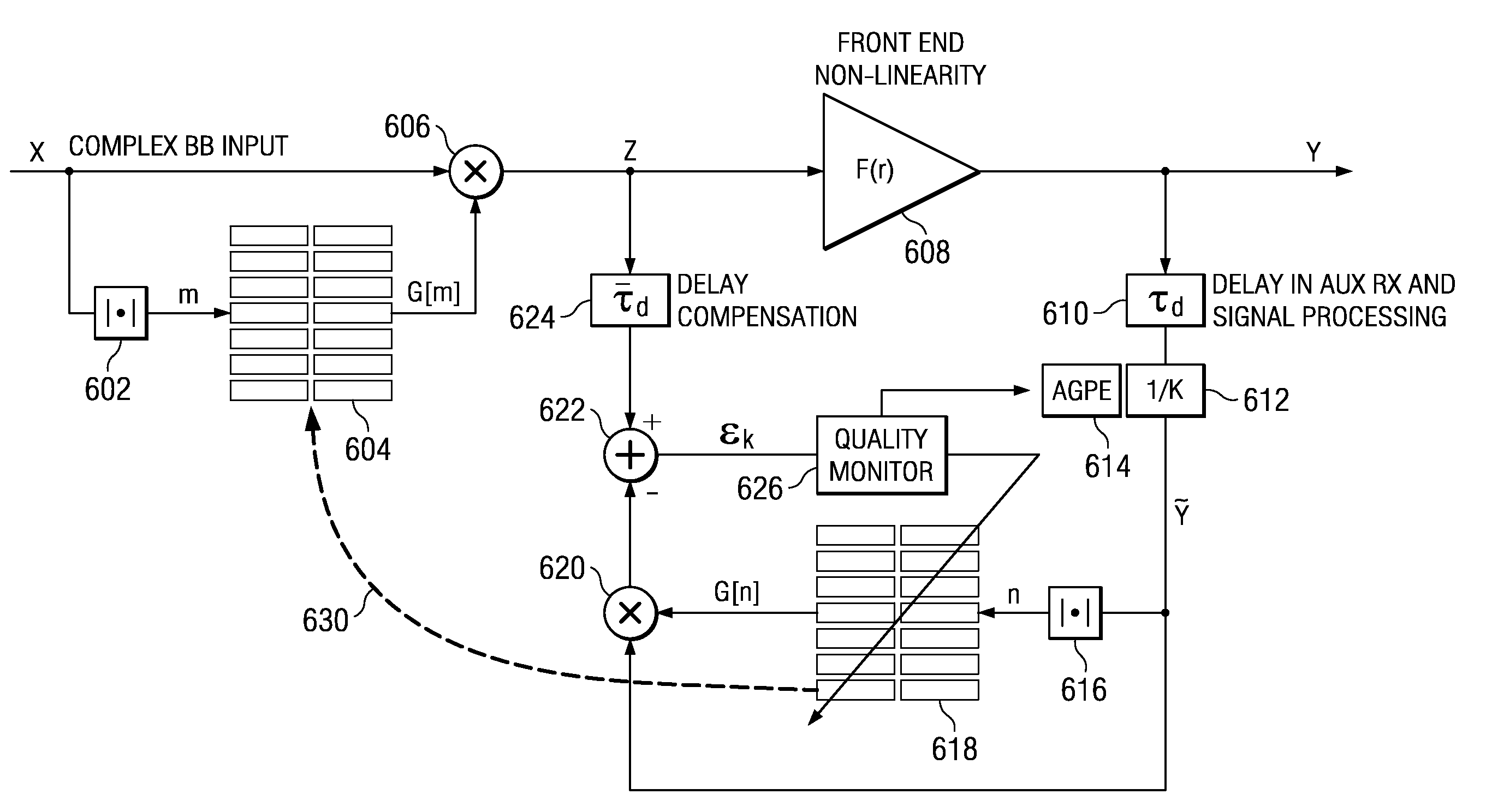
Symbols are transmitted in a Cartesian transmitter by pre-distorting an input signal X having in-phase and quadrature components using a first compensation lookup table operable to hold complex valued entries to carry out in-phase and quadrature compensation pre-distortion with respect to the input signal to form a pre-distorted signal Z. The pre-distorted signal Z is processed to form an output signal Y using a nonlinear element. A complex gain normalization parameter adaptively updated to reflect varying gain of a linear region of the nonlinear element. A normalized feed back signal {tilde over (Y)} is formed using the adaptively updated complex gain normalization parameter. The first compensation lookup table is updated based on the pre-distorted input signal Z and the adaptively normalized feedback signal {tilde over (Y)}.

Description

CLAIM OF PRIORITY UNDER 35 U.S.C. 119(e)[0001]The present application claims priority to and incorporates by reference U.S. Provisional Application No. 61 / 086,261 filed Aug. 5, 2008, entitled “Adaptive Complex Gain Predistorter for a Handset Transmitter with Adaptive Gain / Phase Equalization”.FIELD OF THE INVENTION[0002]The invention is directed, in general, to wireless transmitters and, more specifically, to an apparatus and method for adaptive Cartesian transmitter linearization and a wireless transmitter for use in cellular telephony and communication devices such as Bluetooth, WLAN, etc. using all-digital radio frequency (RF) circuitry.BACKGROUND OF THE INVENTION[0003]Wireless cellular communication networks incorporate large numbers of mobile user equipment (UEs) and a number of base nodes (NodeBs). A NodeB is generally a fixed station, and may also be called a base transceiver system (BTS), an access point (AP), a base station (BS), or some other equivalent terminology. As impr...

Claims


Application Information

Patent Timeline
Patent Type & Authority Patents(United States)
IPC IPC(8): H04B1/04
CPCH03F1/3247H03F3/24H03F2201/3233
Inventor BA, SEYDOU NOUROUWAHEED, KHURRAM
Owner TEXAS INSTR INC
Learn More