
System for optimizing battery pack cut-off voltage

a technology of cut-off voltage and optimization system, applied in the field of batteries, can solve the problems of all-electric and hybrid vehicles, limited service life of battery packs, etc., and achieve the effect of prolonging the useful life of battery packs

Active Publication Date: 2011-11-08
TESLA INC
View PDF11 Cites 74 Cited by
  • Summary
  • Abstract
  • Description
  • Claims
  • Application Information

AI Technical Summary

Benefits of technology

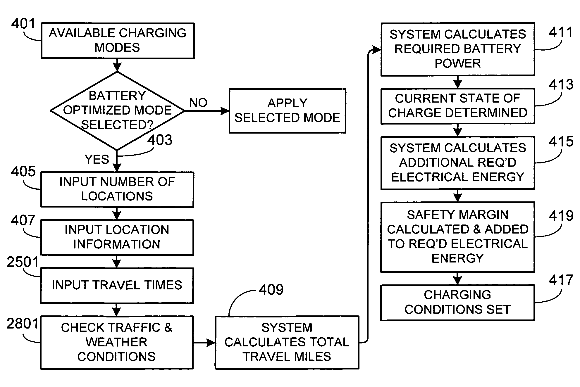
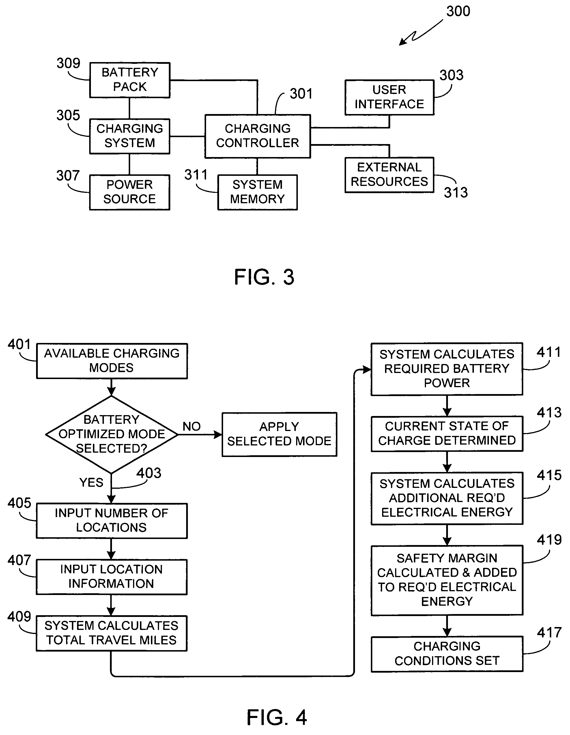
The present invention provides a method and apparatus for controlling the charging system of an all-electric or hybrid vehicle's battery pack based on expected use. This helps to prevent excessive charging levels and extends the battery's lifespan. The charging system controller calculates the total travel miles based on the vehicle's travel plan and the battery's current state of charge, and sets the battery pack charging conditions accordingly. The system can also consider road and traffic conditions, as well as weather conditions, to optimize charging efficiency. The user interface can be a touch-sensitive screen integrated within the vehicle. The method includes inputting a travel plan, calculating the total travel miles, converting the total travel miles to the quantity of electrical energy required, determining the current electrical energy stored in the battery pack, calculating the difference between the required electrical energy and the stored energy, determining the battery power safety margin, setting the battery pack charging conditions, and initiating battery pack charging.

Problems solved by technology

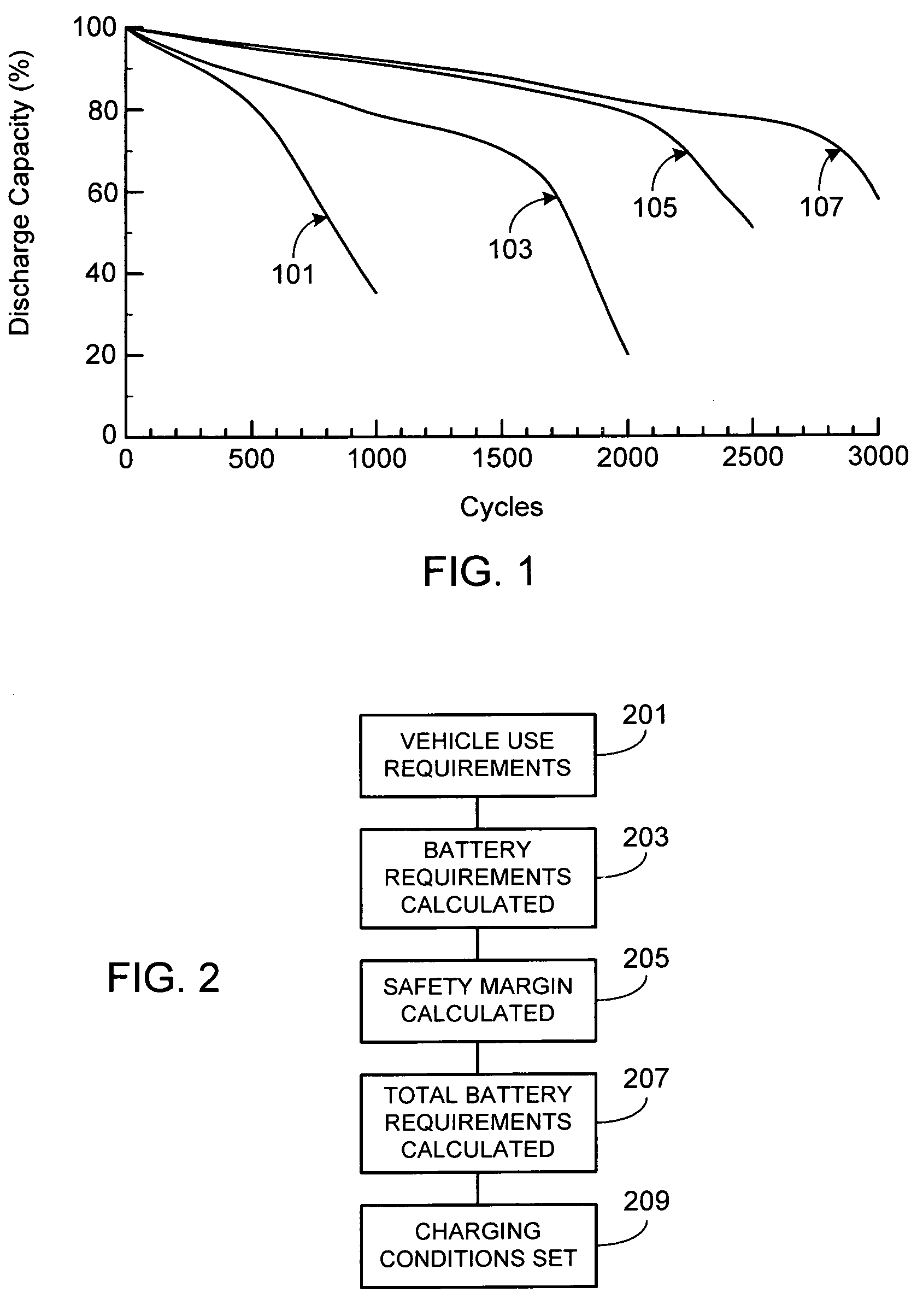
Although rechargeable batteries provide a much longer service life than disposable batteries, their service life is not unlimited.
Due to the high initial cost of rechargeable batteries, expensive products such as laptop computers often incorporate relatively sophisticated power management systems, thereby extending battery life and allowing the use of smaller, lower capacity batteries and / or batteries that utilize less expensive cell chemistries.
All-electric and hybrid vehicles, however, present a number of engineering challenges, primarily due to the need for the rechargeable battery pack of such a vehicle to meet the consumers' expectations relative to performance, range, reliability, lifetime and cost.

Method used


Image

  • System for optimizing battery pack cut-off voltage
  • System for optimizing battery pack cut-off voltage
  • System for optimizing battery pack cut-off voltage

Examples


Embodiment Construction

[0042]In the following text, the terms “battery”, “cell”, and “battery cell” may be used interchangeably and may refer to any of a variety of different rechargeable cell chemistries and configurations including, but not limited to, lithium ion (e.g., lithium iron phosphate, lithium cobalt oxide, other lithium metal oxides, etc.), lithium ion polymer, nickel metal hydride, nickel cadmium, nickel hydrogen, nickel zinc, silver zinc, or other battery type / configuration. The term “battery pack” as used herein refers to multiple individual batteries contained within a single piece or multi-piece housing, the individual batteries electrically interconnected to achieve the desired voltage and current capacity for a particular application. The term “electric vehicle” as used herein refers to either an all electric vehicle, also referred to as an EV, plug-in hybrid vehicles, also referred to as a PHEV, or a hybrid vehicle (HEV), a hybrid vehicle utilizing multiple propulsion sources one of wh...


PUM


Abstract

A method and apparatus for optimizing the level of battery charging required by an electric vehicle is provided. The system includes an interface for the user to input various travel parameters, such as a travel itinerary, which is then used by the battery charging system during charge optimization. In addition to a travel itinerary, the system may be configured to take into account departure times, road conditions, traffic conditions and weather conditions in determining miles to be traveled as well as the electrical energy per mile conversion factors to be used during optimization.

Description

FIELD OF THE INVENTION[0001]The present invention relates generally to batteries and, more particularly, to a system for optimizing the cut-off voltage used during the charging cycle of a battery pack, thereby minimizing the amount of time the batteries are subjected to excessive high voltage.BACKGROUND OF THE INVENTION[0002]Batteries have been used for decades to supply power to a variety of different electrical and electromechanical devices. Early batteries, referred to as disposable batteries, were simply used until depleted and then discarded and replaced with one or more new batteries. A newer type of battery, referred to as a rechargeable battery, is capable of being recharged and then reused, therefore offering economic, environmental and ease-of-use benefits compared to a disposable battery.[0003]Although rechargeable batteries provide a much longer service life than disposable batteries, their service life is not unlimited. Depending upon the type of battery, a rechargeable...

Claims


Application Information

Patent Timeline
Patent Type & Authority Patents(United States)
IPC IPC(8): H02J7/16
CPCB60L3/0046B60L11/1861G06Q50/06B60L11/1859B60L11/185Y02T90/121B60L2250/16B60L2250/18Y02T10/7005Y02T10/7044Y02T10/705Y02T90/128Y02T90/14B60L2240/62B60L2240/64B60L2240/66B60L2240/68B60L2240/70B60L2240/80B60L2250/14Y02T90/16Y02T90/162Y02T10/7291B60L53/11B60L58/14B60L58/15B60L58/16Y02T10/70Y02T10/7072Y02T10/72Y02T90/12
Inventor KELTY, KURT RUSSELLKOHN, SCOTT IRA
Owner TESLA INC
Learn More