
Method of supplying lubricating oil in cold-rolling

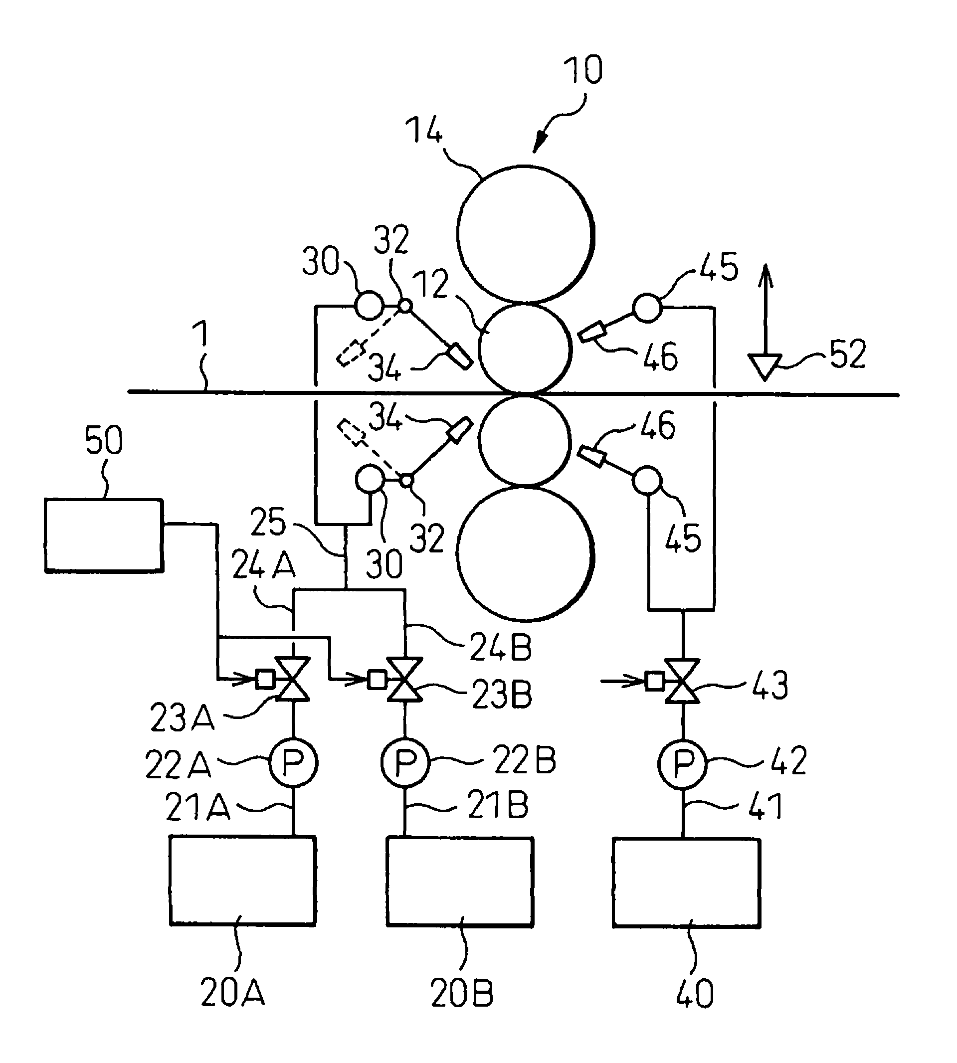
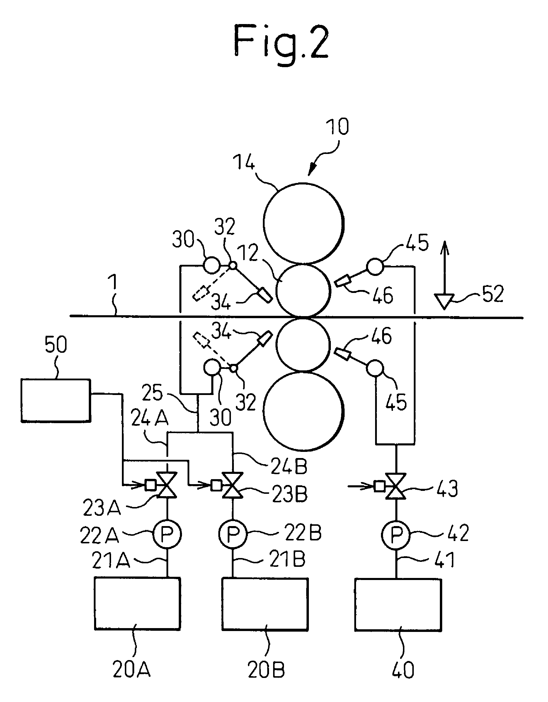
a cold-rolling and lubricating oil technology, which is applied in the direction of crankcase compression engine lubrication, manufacturing tools, machines/engines, etc., can solve the problems of not being able to learn the oil film thickness directly under the roll bite at a certain time, not being able to obtain a suitable oil film thickness, and not being able to estimate or measure the oil film thickness, etc., to achieve stable rolling, improve product quality, and reduce rolling costs

Active Publication Date: 2011-11-01
NIPPON STEEL CORP +1
View PDF7 Cites 3 Cited by
  • Summary
  • Abstract
  • Description
  • Claims
  • Application Information

AI Technical Summary

Benefits of technology

[0022]By high precision lubrication control, a suitable oil film thickness without excess or shortage is formed directly under the roll bite, and the friction coefficient between the rolled material and the work rolls is maintained at a value suitable for the rolling conditions. As a result, it is possible to prevent slip between the rolled material and work rolls and seizure of the rolled material and perform stable rolling. Further, it is possible to reduce the rolling cost and improve the product quality.

Problems solved by technology

In the past, it was not possible to estimate or measure the oil film thickness at the time of emulsion lubrication.
It was possible to arrange an oil film thickness meter at the outlet side of the rolling stand to measure the oil film thickness at the outlet side of the rolling stand, but it was not possible to learn the oil film thickness directly under the roll bite at a certain time.
As a result, with the above conventional lubricating method, it was not possible to obtain a suitable oil film thickness right under the roll bite and not possible to control lubrication with a high precision.
Therefore, regarding the above method (1), since it is for the prediction of the seizing limit, use is not possible at a low speed.
Setting the positions of the lubricating oil supply ends considering the phase transition time is, it is true, effective, but the method of determining the phase transition time is not fixed, therefore there is the problem that the positions cannot be accurately determined.

Method used


Image

  • Method of supplying lubricating oil in cold-rolling
  • Method of supplying lubricating oil in cold-rolling
  • Method of supplying lubricating oil in cold-rolling

Examples


examples

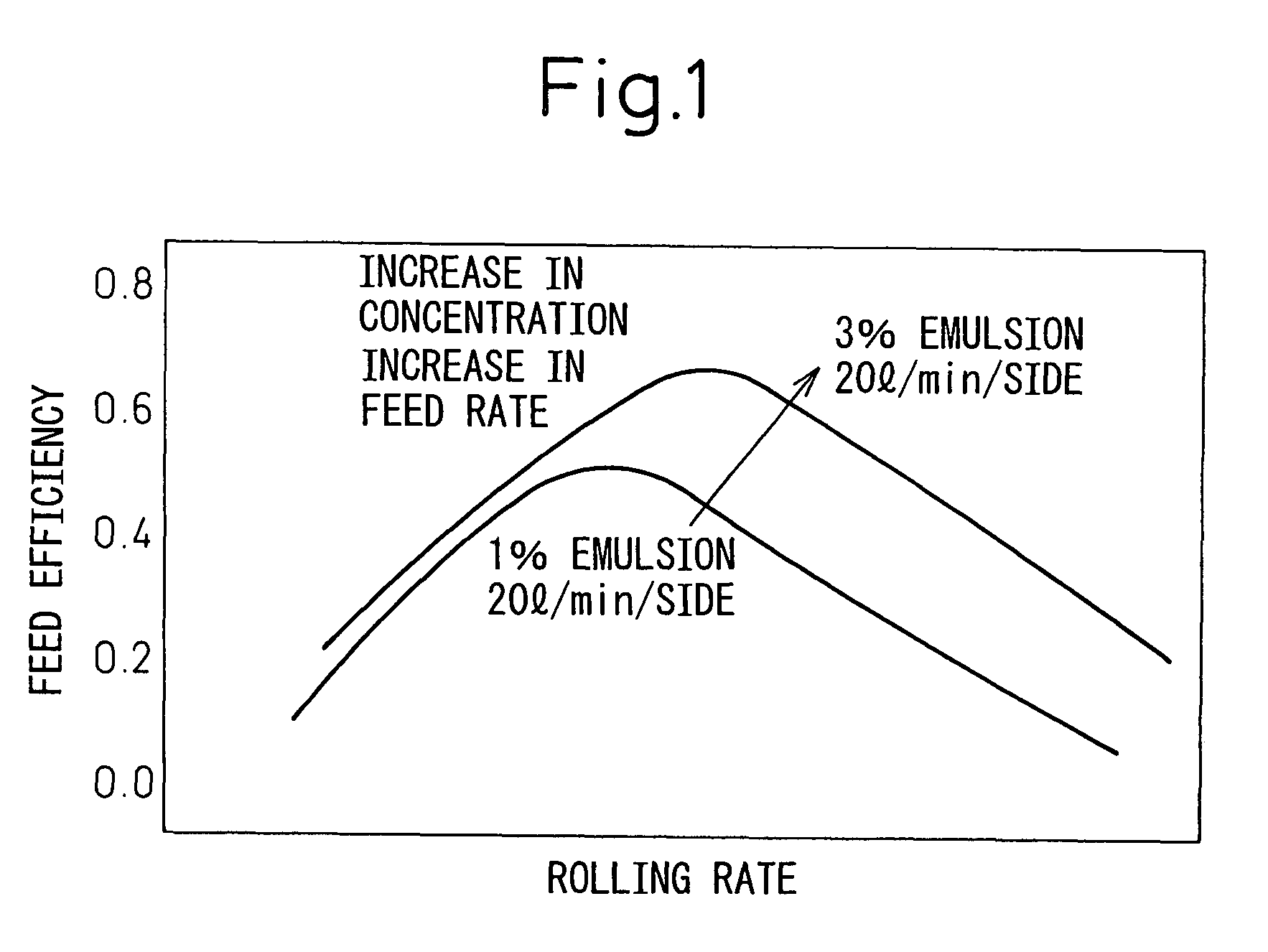
[0062]A single stand 4Hi test mill was used to roll a coil. In this experiment, palm oil was used as the base oil of lubricating oil (emulsion concentration 2%, plateout length 0.3 m, supply rate 1 liter / min per side, sheet width 50 mm) and the supply efficiency was calculated in advance in a preliminary test in the range of conditions of the test. The rolling was performed by accelerating, rolling at a constant 1500 mpm for 10 minutes, then decelerating and ending.

[0063]The present model was applied to a first coil (calculation period of 1 second), whereby a was between 0.11 to 0.23. The sheet was rolled while changing the supply so that the estimated oil film thickness (current 0.38 to 0.48 μm) matched with the target oil film thickness. The target oil film thickness was made an oil film thickness at the time of the limit of occurrence of seizure flaws obtained by operation up to here. When using the present model, rolling was possible without problems such as seizure flaws.

[0064]...


PUM

PropertyMeasurementUnit
widthaaaaaaaaaa
lengthaaaaaaaaaa
thicknessaaaaaaaaaa

Abstract

A method of supplying lubricating oil in cold-rolling by emulsion lubrication, characterized by comprising:using a constant (supply efficiency) obtained under conditions of a specific rolling rate, emulsion supply, emulsion concentration, emulsion temperature, plateout length, rolled material width or roll barrel length, rolling load, grade of the rolled material, and type of lubricating oil and oil film thickness at the time of neat lubrication realized under the specific rolling lubrication conditions to estimate the oil film thickness realized by emulsion lubrication under the specific rolling lubrication conditions andcontrolling at least one of the emulsion supply, emulsion concentration, emulsion temperature, and plateout length so that the estimated oil film thickness matches with the target oil film thickness.

Description

TECHNICAL FIELD[0001]The present invention relates to a method of supplying lubricating oil in cold-rolling, more particularly relates to a method of supplying lubricating oil by emulsion lubrication.BACKGROUND ART[0002]In cold-rolling of steel sheet, from the viewpoints of stabilization of the rolling operation, the shape and surface quality of the product, prevention of seizure, the roll lifetime, etc., it is necessary to maintain the friction coefficient between the rolled material (steel sheet) and the work rolls at a suitable value. To obtain a suitable friction coefficient, a lubricating oil suitable for the grade, dimensions, and rolling conditions of the rolled sheet is selected and supplied at the inlet side of the rolling stand to the rolled material or rolls.[0003]At the cold-rolling of a steel sheet, in general emulsion lubrication is used. To obtain a suitable friction coefficient, a model is used to control the emulsion supply rate or emulsion concentration.[0004]As me...

Claims


Application Information

Patent Timeline
Patent Type & Authority Patents(United States)
IPC IPC(8): B21B27/06B21B45/02
CPCB21B37/00B21B45/0266B21B1/28B21B1/36B21B27/10B21B45/0251B21B45/02B21B1/22
Inventor TAKAHAMA, YOSHIKISHIRAISHI, TOSHIYUKIOGAWA, SHIGERUVANEL, LUCHAURET, GUY
Owner NIPPON STEEL CORP
Learn More