
Selector circuit

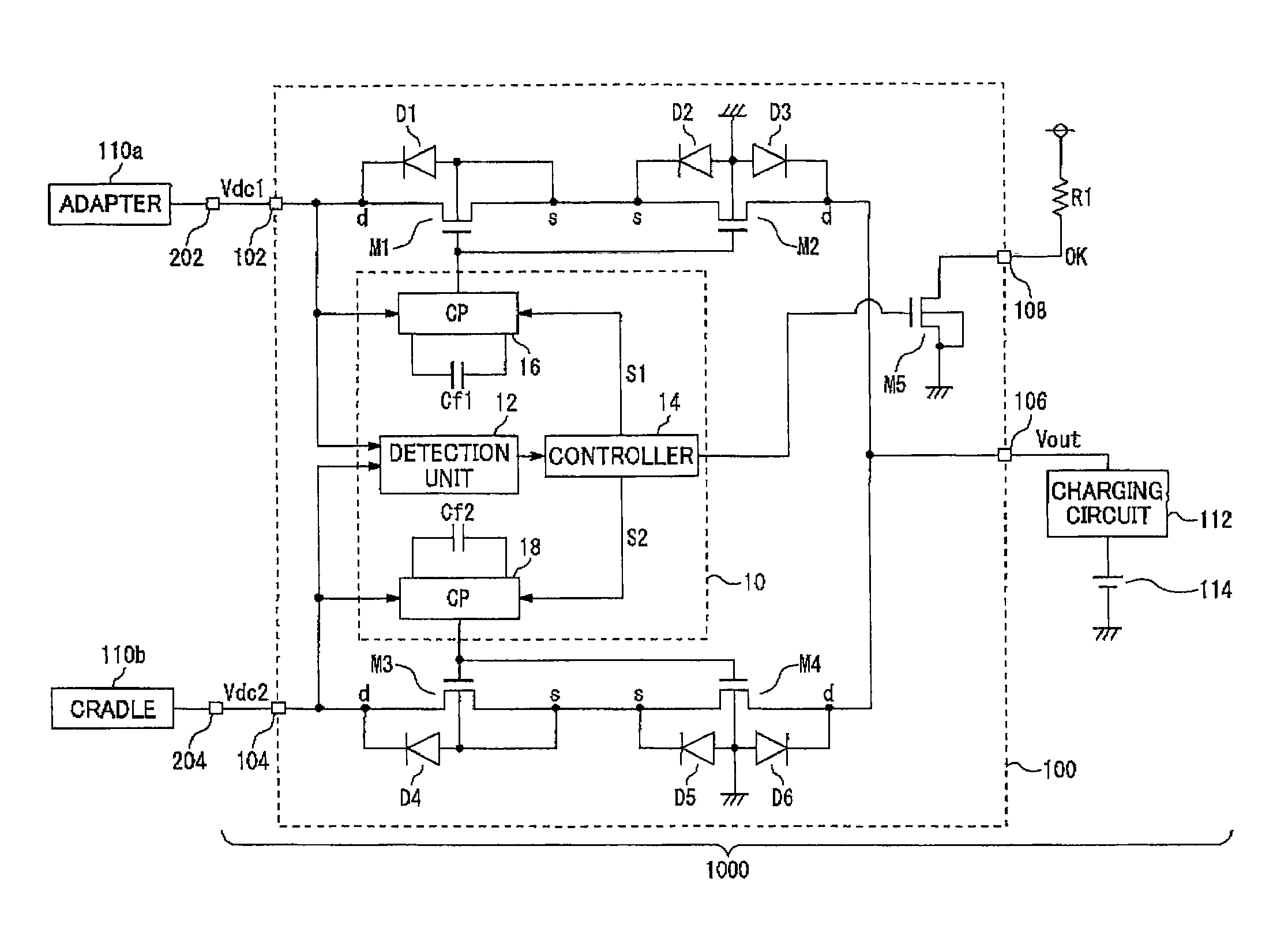
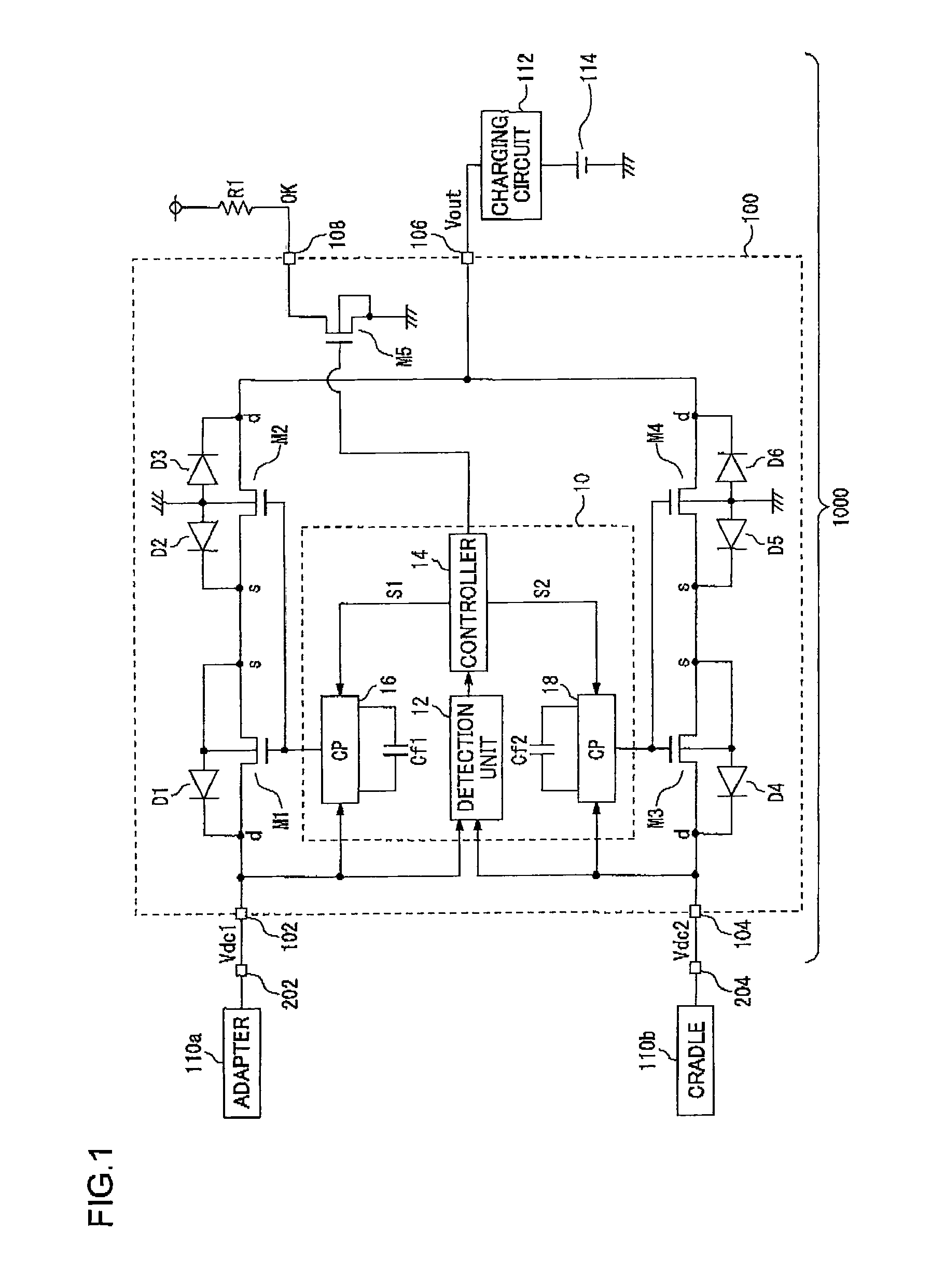
a technology of circuits and circuits, applied in the field of circuits, can solve the problems of increasing circuit area, reducing output voltage from input voltage, and increasing the number of components, and achieve the effect of preventing reverse current flow

Active Publication Date: 2011-10-25
ROHM CO LTD
View PDF9 Cites 89 Cited by
  • Summary
  • Abstract
  • Description
  • Claims
  • Application Information

AI Technical Summary

Benefits of technology

The present invention provides a selector circuit that selects one of multiple voltages and outputs the selected voltage. The circuit includes a first input terminal, a second input terminal, an output terminal, and a control unit that selects the first or second input voltage to output. The circuit also includes first and second MOSFETs, third and fourth MOSFETs, and a control unit that selects the first or second MOSFETs to output. The MOSFETs are arranged in opposing directions to prevent reverse current flow. The circuit has overvoltage protection and low-voltage lockout functions. The MOSFETs may be N-channel or P-channel MOSFETs. The control unit may include charge pump circuits to step up the input voltage. The invention also includes an electronic device with a detachable power supply and a charging circuit. The technical effects of the invention include improved voltage selection and protection against voltage drops.

Problems solved by technology

However, the circuit described in Patent document 1 has a problem in that the output voltage is reduced from that of the input voltage by the forward voltage Vf of the diode.
Furthermore, in a case in which the diodes are provided in the form of external components, such a circuit has another problem of an increase in the circuit area and an increased number of components.

Method used


Image

  • Selector circuit
  • Selector circuit

Examples


Embodiment Construction

[0027]The invention will now be described based on preferred embodiments which do not intend to limit the scope of the present invention but exemplify the invention. All of the features and the combinations thereof described in the embodiment are not necessarily essential to the invention.

[0028]In the present specification, the state represented by the phrase “the member A is connected to the member B” includes: a state in which the member A and the member B are physically and directly connected to each other; and a state in which the member A and the member B are indirectly connected to each other via another member that does not affect the electric connection therebetween.

[0029]In the same way, the state represented by the phrase “the member C is provided between the member A and the member B” includes a state in which these members are indirectly connected to each other via another member that does not affect the electric connection therebetween, in addition to the state in which...


PUM


Abstract

A selector circuit outputs one of a first input voltage or a second input voltage via an output terminal. A first transistor and a second transistor are provided in series between a first input terminal and the output terminal. A third transistor and a fourth transistor are provided in series between a second input terminal and the output terminal. A control unit controls the ON / OFF operations of the first transistor through the fourth transistor. The back gates of the first transistor and the second transistor are connected such that at least one body diode of the first transistor M1 and at least one body diode of the second transistor are arranged in opposing directions. The back gates of the third transistor and the fourth transistor are connected in the same way.

Description

BACKGROUND OF THE INVENTION[0001]1. Field of the Invention[0002]The present invention relates to a selector circuit which receives multiple input voltages, selects one of the input voltages thus received, and outputs the voltage thus selected.[0003]2. Description of the Related Art[0004]In recent years, electronic devices are known that receive power supply voltage from an external power supply and charge a built-in secondary battery using the power supply voltage. In some cases, such an electronic device includes multiple power supply input terminals for receiving the external power supply. For example, a cellular phone terminal includes a power supply input terminal for a cradle (desktop holder) and another power supply input terminal for an adapter, separately.[0005]Such an electronic device requires a selector circuit which selects one of the power supply voltages supplied to the multiple power supply input terminals, and outputs the voltage thus selected to a charging circuit. ...

Claims


Application Information

Patent Timeline
Patent Type & Authority Patents(United States)
IPC IPC(8): H02J7/00
CPCH02J7/0055Y10T307/50H02J2207/40H02J7/02H02J7/00308H02J7/00309
Inventor TAMEGAI, YOICHIYOKOMIZO, ICHIRONAKAHARA, HIRONORI
Owner ROHM CO LTD
Learn More