
Navigation services based on position location using broadcast digital television signals

a technology of broadcast digital television and position location, applied in the direction of navigation instruments, instruments, two-way working systems, etc., can solve the problems of information being solicited or unsolicited, and neither the service is necessarily provided to the user of the device, and achieves strong and larger bandwidth signals, simple and inexpensive implementation, and excellent coverage

Inactive Publication Date: 2011-10-18
TRUE POSITION INC
View PDF138 Cites 25 Cited by
  • Summary
  • Abstract
  • Description
  • Claims
  • Application Information

AI Technical Summary

Benefits of technology

"The present invention provides a service based on the location of a device using pseudo-ranges between the device and digital television (DTV) transmitters. DTV signals are used for position location because they have excellent coverage, are simple and inexpensive to implement, and have advantages over GPS alternatives. The device can be stationary or mobile. The service can be provided to the user of the device or at the location of the device. The device location can be mapped into different geographic domains and the appropriate service can be provided. The functions can be allocated among different entities in different ways. The invention can be implemented in software or hardware. The technical effects of the invention include improved location-based services and cost-effectiveness."

Problems solved by technology

Nor is the service necessarily provided to the user of the device or at the location of the device.
For example, with information-based services, the information may be solicited or unsolicited.

Method used


Image

  • Navigation services based on position location using broadcast digital television signals
  • Navigation services based on position location using broadcast digital television signals
  • Navigation services based on position location using broadcast digital television signals

Examples


Embodiment Construction

Overview

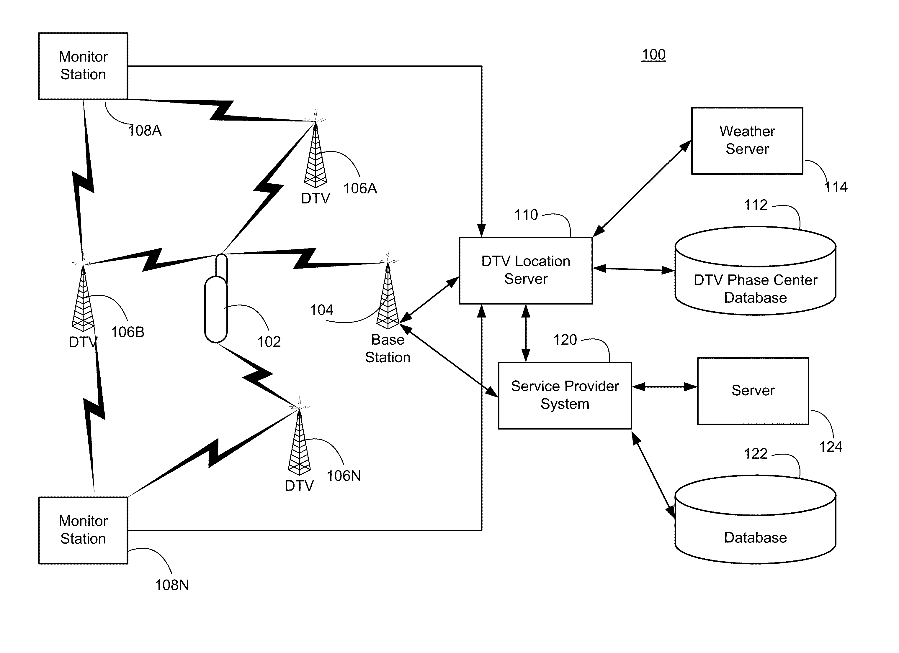
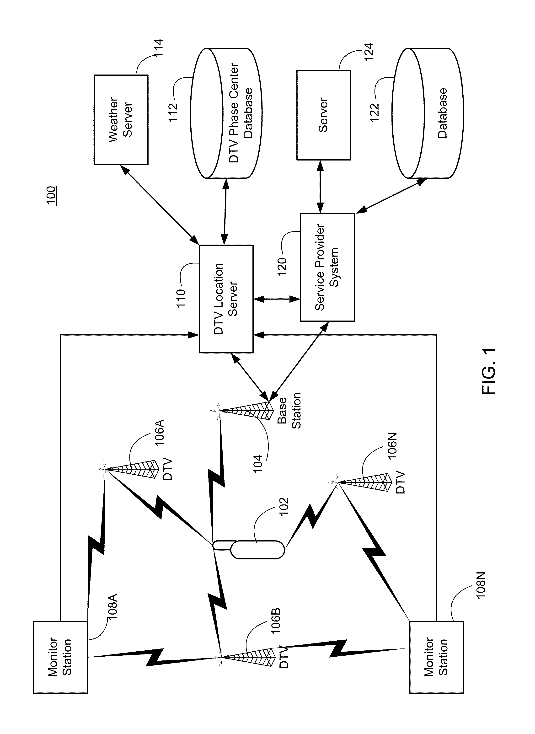
FIG. 1 depicts a system 100 suitable for implementing the present invention. The system 100 includes a device 102 operated by a user, DTV transmitters 106A-106N, monitor stations 108A-108N, DTV location server 110, and service provider system 120. The DTV transmitters 106 broadcast DTV signals, including to device 102 and to the monitor stations 108. The DTV location server 110 is linked to the user device 102 (via base station 104 in this example) and to the monitor stations 108. The service provider system 120 is linked to the DTV location server 110 and to the user device 102 (also via base station 104 in this example).

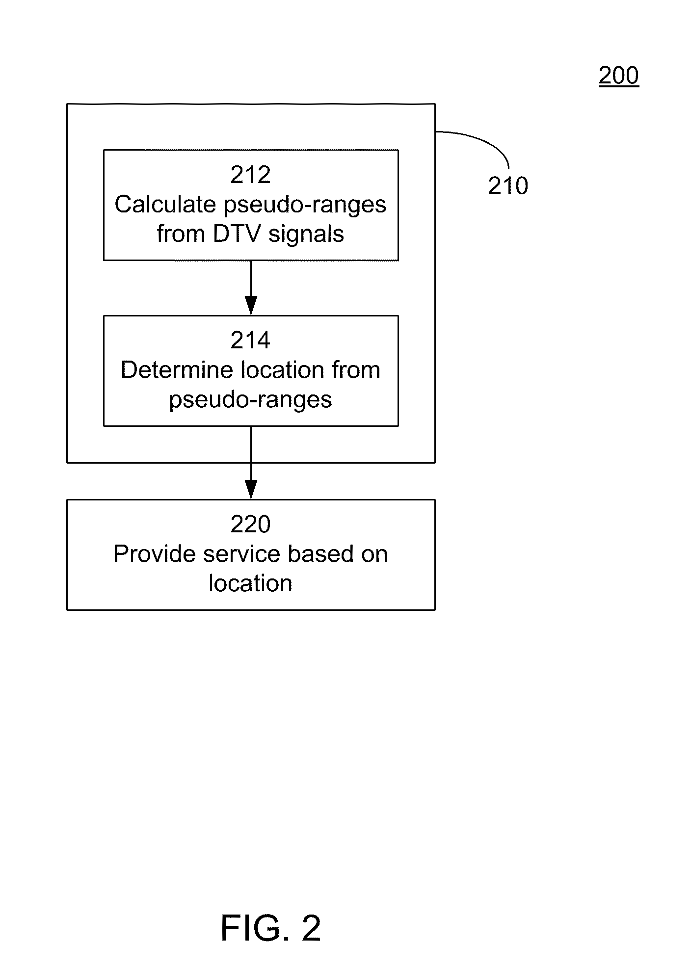
FIGS. 2-3 are flow diagrams illustrating methods according to the present invention. Generally speaking, as shown in FIG. 2, the location of device 102 is determined 210 using DTV signals which are received by the user device 102. A service which depends on this location is provided 220.

In the example of FIG. 1, the DTV transmitters 106, monitor stations 10...


PUM


Abstract

A service depends on the location of a device. The device location is determined using DTV signals. More specifically, the device location is determined based on pseudo-ranges between the device and a plurality of digital television (DTV) transmitters and the pseudo-ranges are determined based on broadcast DTV signals received by the device from the DTV transmitters. Examples of DTV signals include the American Television Standards Committee (ATSC) signals, the European Telecommunications Standards Institute Digital Video Broadcasting-Terrestrial (DVB-T) signals and the Japanese Integrated Service Digital Broadcasting-Terrestrial (ISDB-T) signals.

Description

BACKGROUND OF THE INVENTION1. Field of the InventionThis invention relates generally to position location and providing services based on position location. More specifically, it relates to providing services in cases where the position location is based on DTV signals.2. Description of the Related ArtThere have long been methods of two-dimensional latitude / longitude position location systems using radio signals. In wide usage have been terrestrial systems such as Loran C and Omega, and a satellite-based system known as Transit. Another satellite-based system enjoying increased popularity is the Global Positioning System (GPS).Initially devised in 1974, GPS is widely used for position location, navigation, survey, and time transfer. The GPS system is based on a constellation of 24 on-orbit satellites in sub-synchronous 12 hour orbits. Each satellite carries a precision clock and transmits a pseudo-noise signal, which can be precisely tracked to determine pseudo-range. By tracking 4 ...

Claims


Application Information

Patent Timeline
Patent Type & Authority Patents(United States)
IPC IPC(8): G01C21/00H04N7/173G01S5/00G01S5/02G01S5/14G01S19/46H04B7/26H04H1/00H04M3/42H04N7/24H04Q7/34
CPCH04N21/2662H04N21/2668H04N21/41422H04N21/615H04N21/8126G01C21/206G01S5/0036G01S5/0054G01S5/0081G01S5/021G01S5/0215G01S5/0221G01S5/14G01S19/46H04N21/25841A63F2300/205G01S5/145G01S5/0218G01S5/02216
Inventor PIERCE, MATTHEW D.RABINOWITZ, MATTHEW
Owner TRUE POSITION INC
Learn More