Automated frequency compensation for remote synchronization
What is Al technical title?
Al technical title is built by PatSnap Al team. It summarizes the technical point description of the patent document.
a remote synchronization and frequency compensation technology, applied in the field of automatic frequency compensation for remote synchronization, can solve the problems of providing a less desirable clock signal, and achieve the effects of reliable remote synchronization, low phase noise, and narrow loop bandwidth
Inactive Publication Date: 2008-03-18
NORTH SOUTH HLDG
View PDF19 Cites 11 Cited by
Summary
Abstract
Description
Claims
Application Information
AI Technical Summary
This helps you quickly interpret patents by identifying the three key elements:
Problems solved by technology
Method used
Benefits of technology
[0025]A technical advantage of the present invention is that an inexpensive controllable oscillator, such as an inexpensive VCO having a DAC coupled thereto to drive the control voltage, may be utilized to provide reliable remote synchronization of a frequency over a relatively large drift range.
[0026]A further technical advantage of the present invention is provided in implementing the AFC with a substantially standard PLL having a very narrow loop bandwidth. This provides a desired low phase noise characteristic in a relatively inexpensive and simple to implement system.
[0027]A still further technical advantage is provided by the present invention in a sweep mode operation that allows the oscillator to be stepped through various operating settings and provide the ability to hunt through a given spectrum, such as either side of a selected nominal frequency, for the lock range at which a PLL can then lock onto the master clock.
[0028]A yet further technical advantage is provided by the ability of the present invention to provide statistics useful for performance monitoring and trouble shooting.
[0029]The foregoing has outlined rather broadly the features and technical advantages of the present invention in order that the
Problems solved by technology
However, the Murata part has an aging spec 20 times greater (worse) that a precision part and thus would typically provide a less desirable clock signal.
Method used
Image
Click on the blue label to locate the original text in one second.
Reading with bidirectional positioning of images and text.
Examples
Embodiment Construction
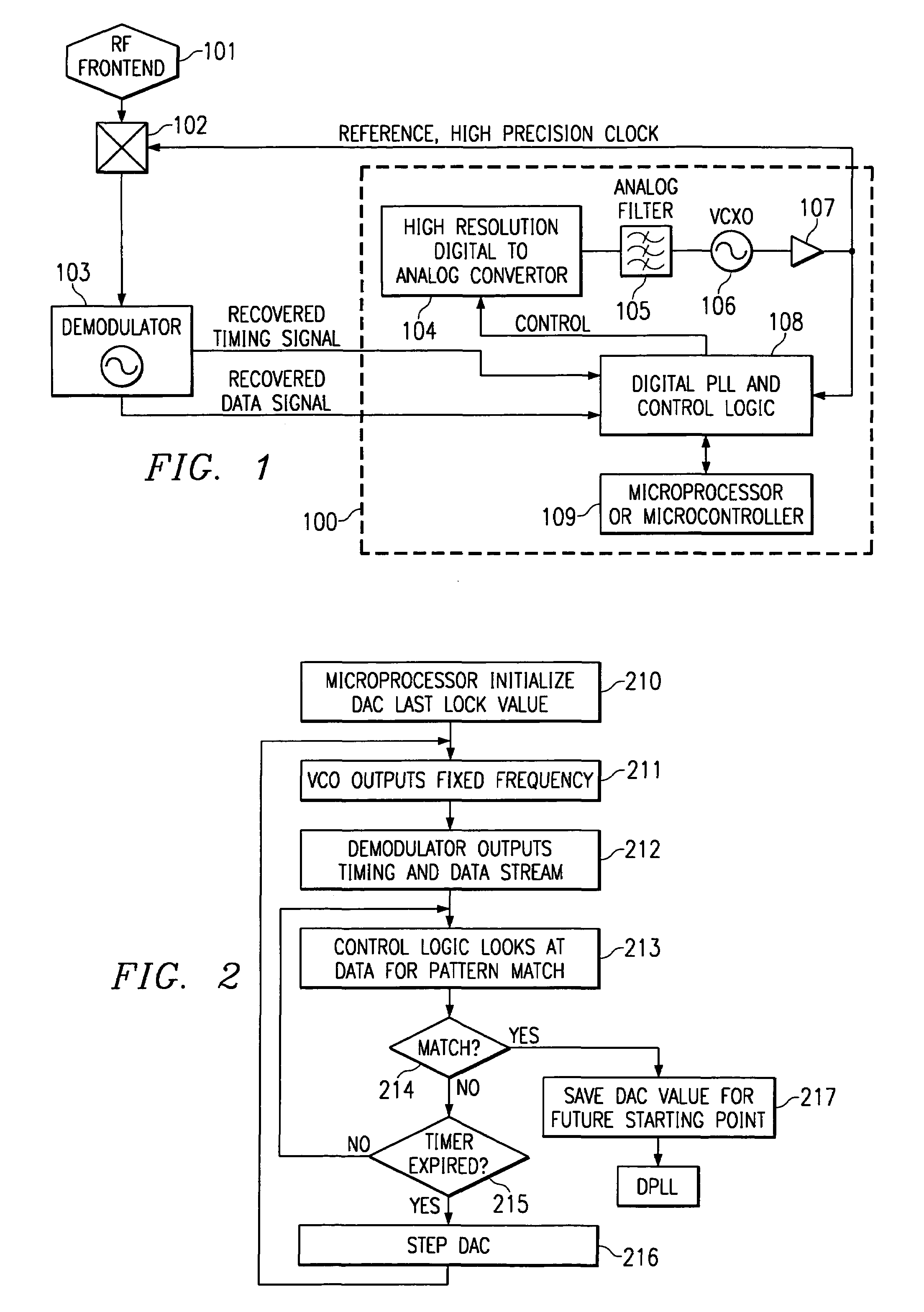
[0034]Directing attention to FIG. 1, an RF receiver circuit adapted according to the present invention is shown having RF front end 101 and demodulator 103. Automatic frequency control (AFC) 100 of the present invention is coupled to a received signal provided by RF front end 101 by mixer 102 to allow demodulator 103 to recover information modulated with a particular carrier frequency. Accordingly, in the preferred embodiment of FIG. 1, a local VCO, which provides a reference frequency, is used to tune a receiver based on a recovered timing signal from the demodulator.
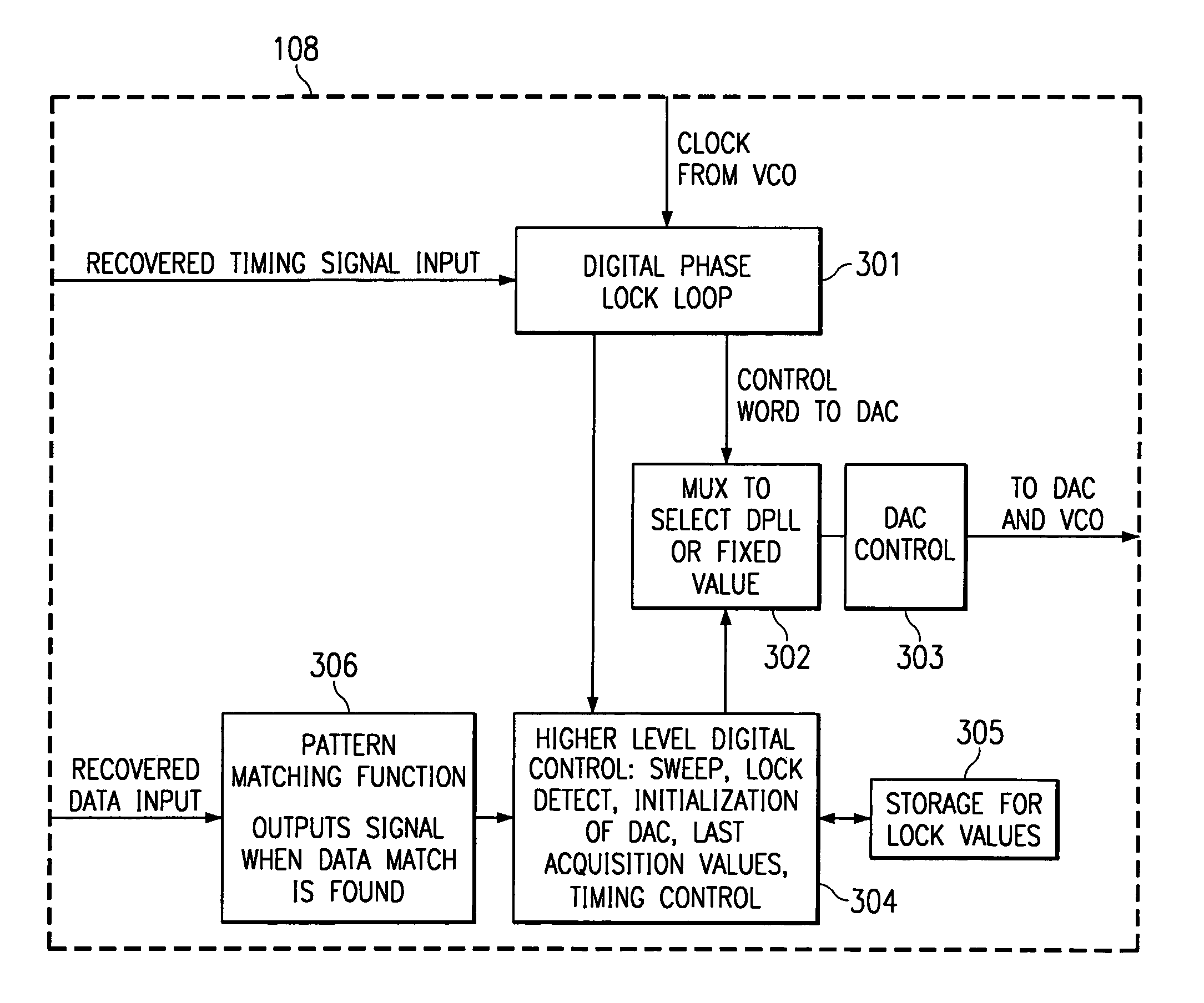
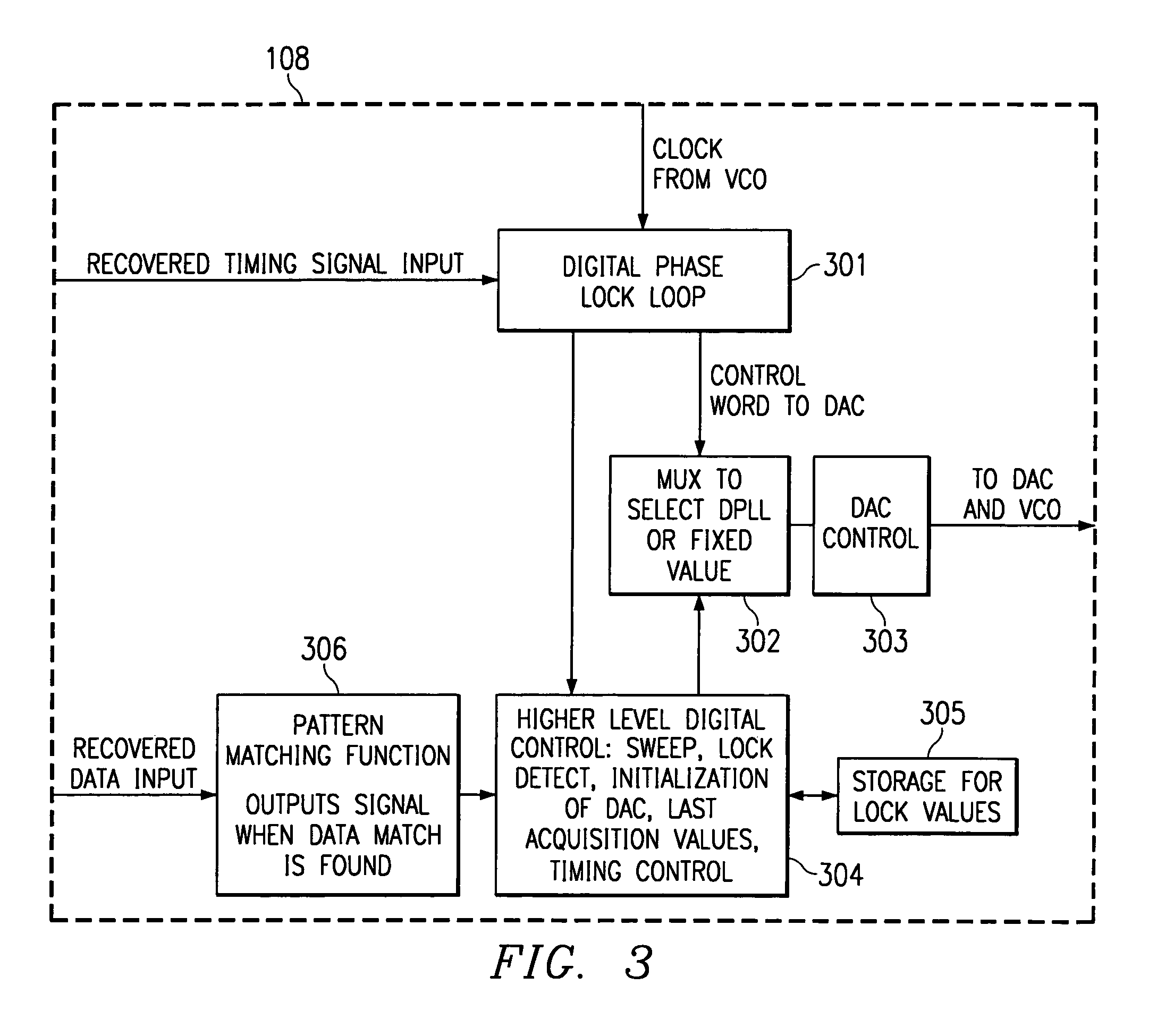
[0035]The preferred embodiment AFC 100 of FIG. 1 includes DAC 104, filter 105, VCO 106, clock signal generator 107, DPLL and control logic 108, and controller 109. VCO 106 provides a controllable reference frequency and is coupled to clock signal generator 107 to operate therewith to provide a controllable clock signal. This controllable clock signal is preferably provided to RF circuitry, such as through mixer 102, to...
PUM
Abstract
Systems and methods for providing frequency compensation over a wide range of frequency drift are shown. The preferred embodiment utilizes a sweep mode function to provide frequency compensation over a range of frequency drift broader than the frequency drift accommodated by a phase lock loop, without increasing the noise characteristics of the phase lock loop. Accordingly, the preferred embodiment operates in a phase lock loop mode while frequency drift can be compensated for by the lock range of the phase lock loop circuitry. The preferred embodiment operates in sweep mode to step through a range of offset frequencies to position the phase lock loop mode where frequency drift can be compensated for by the lock range of phase lock loop circuitry. Additionally, a preferred embodiment of the present invention includes a drift mode in order to monitor frequency offset information, such as may be used in performing sweep mode functions and / or other control or management functions.
Description
RELATED APPLICATIONS[0001]The present application is a divisional of, claims benefit of, and is with commonly assigned U.S. patent application Ser. No. 09 / 488,313, filed Oct. 20, 2000 now Pat. No. 6,823,031, entitled “Automated Frequency Compensation for Remote Synchronization”, which is related to and co-pending with commonly assigned U.S. patent application Ser. No. 08 / 740,332, now Pat. No. 6,016,313, entitled “System and Method for Broadband Millimeter Wave Data Communication”, and its co-pending and commonly assigned divisional patent applications Ser. No. 09 / 434,832, now Pat. No. 7,054,289, entitled “System and Method for Broadband Millimeter Wave Data Communication”, 09 / 434,815, now Pat. No. 6,735,452, entitled “System and Method for Broadband Millimeter Wave Data Communication”, 09 / 434,816, now Pat. No. 6,748,240, entitled “System and Method for Broadband Millimeter Wave Data Communication”, and 09 / 434,707, now Pat. No. 6,778,516, entitled “System and Method for Broadband Mil...
Claims
Application Information
Patent Timeline
Application Date:The date an application was filed.
Publication Date:The date a patent or application was officially published.
First Publication Date:The earliest publication date of a patent with the same application number.
Issue Date:Publication date of the patent grant document.
PCT Entry Date:The Entry date of PCT National Phase.
Estimated Expiry Date:The statutory expiry date of a patent right according to the Patent Law, and it is the longest term of protection that the patent right can achieve without the termination of the patent right due to other reasons(Term extension factor has been taken into account ).
Invalid Date:Actual expiry date is based on effective date or publication date of legal transaction data of invalid patent.