
Amorphous submicron particles

a technology of amorphous solids and submicron particles, which is applied in the field of pulverulent amorphous solids, can solve the problems of inability to achieve the effect and inability to mill to a median particle diameter of less than 1 m

Inactive Publication Date: 2011-10-18
EVONIK OPERATIONS GMBH
View PDF5 Cites 4 Cited by
  • Summary
  • Abstract
  • Description
  • Claims
  • Application Information

AI Technical Summary

Benefits of technology

[0038]A further advantage of the process according to the invention in one of its preferred embodiments is that the milling can take place simultaneously with the drying so that, for example, a filter cake can be directly further processed. This saves an additional drying step and simultaneously increases the space-time yield.

Problems solved by technology

However, the use of steam has the disadvantage that condensation may occur in the entire milling system, particularly during the startup of the mill, which as a rule results in the formation of agglomerates and crusts during the milling process.
Milling to a median particle diameter of less than 1 μm is, however, not possible with this technique.
A large fraction of large particles, i.e. >2 μm, is disadvantageous for applications in coating systems since as a result thin coats having a smooth surface cannot be produced.
It is not possible with the aid of this technology to isolate a finely divided, agglomerate-free dry product from these suspensions, in particular without changing the porosymmetric properties.

Method used


Image

  • Amorphous submicron particles
  • Amorphous submicron particles
  • Amorphous submicron particles

Examples


examples

[0121]The reaction conditions and the physicochemical data of the precipitated silicas according to the invention were determined by the following methods:

Particle Size Determination

[0122]In the following examples, particle sizes which were measured by one of the three following methods are mentioned at various points. The reason for this is that the particle sizes mentioned there extend over a very wide particle size range (˜100 nm to 1000 μm). Depending on the expected particle size of the sample to be investigated, a different method from among the three particle size measurement methods may therefore be suitable in each case.

[0123]Particles having an expected median particle size of about >50 μm were determined by means of screening. Particles having an expected median particle size of about 1-50 μm were investigated by means of the laser diffraction method, and TEM analysis+image evaluation were used for particles having an expected median particle size of <1.5 μm.

[0124]The met...

examples 1-3

Milling According to the Invention

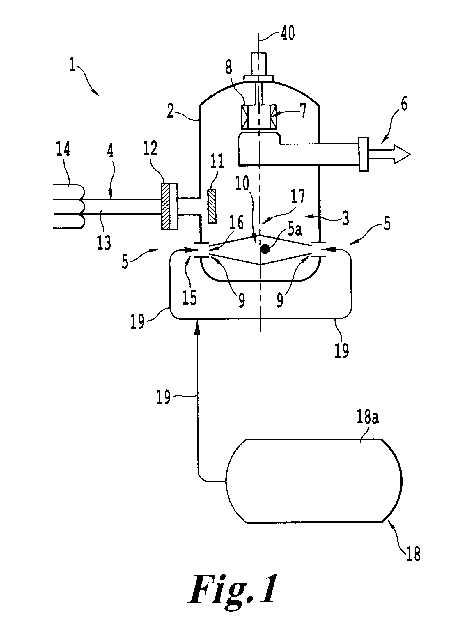
[0200]For preparation for the actual milling with superheated steam, a fluidized-bed opposed jet mill according to FIGS. 1, 2a and 3a was first heated to a mill exit temperature of about 105° C. via the two heating nozzles 5a (only one of which was shown in FIG. 1) through which hot compressed air at 10 bar and 160° C. was passed.

[0201]For depositing the milled material, a filter unit (not shown in FIG. 1) was connected downstream of the mill, the filter housing of which filter unit was heated in the lower third indirectly via attached heating coils by means of 6 bar saturated steam, likewise for preventing condensation. All apparatus surfaces in the region of the mill, of the separation filter and of the supply lines for steam and hot compressed air were specially insulated.

[0202]After the desired heat-up temperature had been reached, the supply of hot compressed air to the heating nozzles was switched off and the supply of superheated steam (38 ba...


PUM

PropertyMeasurementUnit
median particle diameteraaaaaaaaaa
particle diametersaaaaaaaaaa

Abstract

A process for milling amorphous solids using a milling apparatus can result in particles having a median particle diameter d50 of <1.5 μm. The process includes: operating a mill in a milling phase with an operating medium selected from the group consisting of gas, vapor, steam, a gas containing steam and mixtures thereof, and heating a milling chamber in a heat-up phase before the actual operation with the operating medium in such a way that a temperature in the milling chamber, the mill exit or both, is higher than a dew point of the operating medium.

Description

BACKGROUND OF THE INVENTION[0001]1. Field of the Invention[0002]The invention relates to pulverulent amorphous solids having a very small median particle size and a narrow particle size distribution, a process for the preparation thereof and the use thereof.[0003]2. Discussion of the Background[0004]Finely divided, amorphous silica and silicates have been produced industrially for decades. As a rule, the very fine milling is carried out in spiral jet mills or opposed jet mills using compressed air as milling gas, e.g. EP 0139279.[0005]It is known that the achievable particle diameter is proportional to the square root of the inverse of the impact velocity of the particles. The impact velocity in turn is predetermined by the jet velocity of the expanding gas jets of the respective milling medium from the nozzles used. For this reason, superheated steam can preferably be used for generating very small particle sizes, since the acceleration power of steam is about 50% greater than that...

Claims


Application Information

Patent Timeline
Patent Type & Authority Patents(United States)
IPC IPC(8): B32B5/16
CPCB02C19/06B02C19/068Y10T428/29Y10T428/2982Y10T428/259B02C19/186B02C19/005B02C23/08B02C21/00
Inventor MEIER, KARLBRINKMANN, ULRICHPANZ, CHRISTIANMISSELICH, DORISGOETZ, CHRISTIAN
Owner EVONIK OPERATIONS GMBH
Learn More