
Method for increasing the efficiency of a combined gas/steam power station with integrated gasification combined cycle

a technology of gasification combined cycle and combined gas, which is applied in the direction of machines/engines, liquefaction, light and heating apparatus, etc., can solve the problems of power and efficiency loss which accompanies air fractionation and is, therefore, noticeably reduced, and achieves the effect of improving steam turbine efficiency and expanding back pressur

Inactive Publication Date: 2011-09-20
SIEMENS AG
View PDF15 Cites 1 Cited by
  • Summary
  • Abstract
  • Description
  • Claims
  • Application Information

AI Technical Summary

Benefits of technology

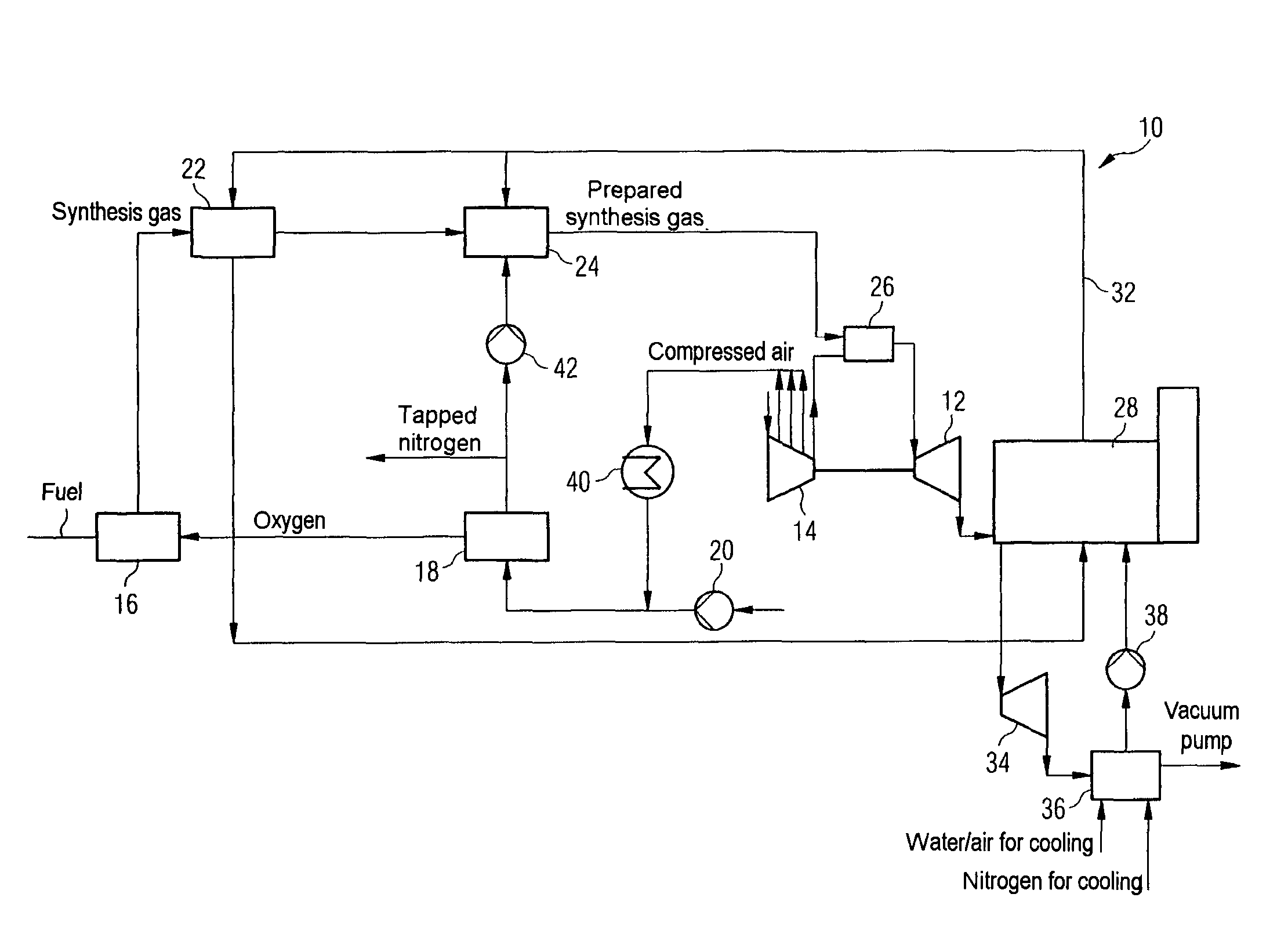
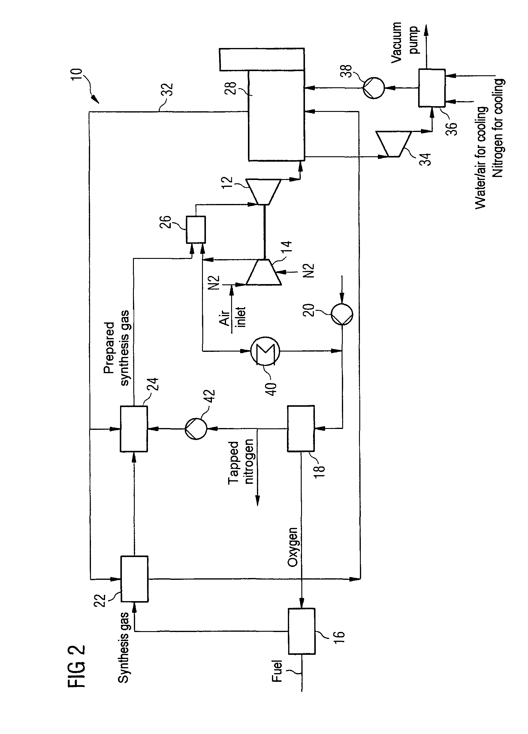
[0012]This problem is solved according to the invention by the method mentioned at the start for increasing the efficiency of a combined gas and steam power generating plant with integrated fuel gasification (IGCC power generating plant), which has a gas turbine compressor and an air fractionation plant with a predetermined operating pressure, in which compressed air is extracted from the gas turbine compressor at a pressure level which is adapted to the operating pressure of the air fractionation plant, in which the extracted air is then fed to the air fractionation plant, in which the air is broken down into its individual component parts, especially into oxygen and nitrogen, the nitrogen produced in the air fractionation plant is extracted from the air fractionation plant, and at least a part of the extracted nitrogen volume is used as cooling medium. The cooling air which is saved by this leads to an increase in efficiency.
[0023]In a further practical development of the method according to the invention, the part of the extracted nitrogen volume which is used as cooling medium can also be used alternatively as additional cooling medium for a condenser of a steam turbine of the combined gas and steam power generating plant with integrated fuel gasification, as a result of which the expansion back pressure after the last steam turbine stage is further reduced, and so a power output gain and an improvement of the steam turbine efficiency can be achieved.

Problems solved by technology

The power and efficiency loss which accompanies the air fractionation is, therefore, noticeably reduced.

Method used


Image

  • Method for increasing the efficiency of a combined gas/steam power station with integrated gasification combined cycle
  • Method for increasing the efficiency of a combined gas/steam power station with integrated gasification combined cycle
  • Method for increasing the efficiency of a combined gas/steam power station with integrated gasification combined cycle

Examples


Embodiment Construction

[0028]The IGCC power generating plant 10, which is shown schematically in FIG. 1, comprises inter alia a gas turbine 12 and a gas turbine compressor 14 connected ahead of the gas turbine 12. Fuel, such as hard coal, is gasified in a gasification unit 16 for the production of a synthesis gas. The oxygen required for the gasification is produced in an air fractionation plant 18, in which oxygen is produced from air by fractional distillation. As a rule, the air is taken from the environment, and, by a gas turbine compressor and / or auxiliary compressor, is introduced via a compressor 20 into the air fractionation plant 18 and compressed to the pressures required for the fractional distillation.

[0029]The synthesis gas which is produced in the gasification unit 16 is cooled down in a synthesis gas cooling unit 22 before the further treatment, and is then fed to a gas purification unit 24. In the gas purification unit 24, filters (not shown) first hold back ash particulate, then carbon di...


PUM


Abstract

The invention relates to a method for increasing the efficiency of a combined gas / steam power station (10) with integrated gasification combined cycle. Said power station comprises a gas turbine compressor (14) and an air-separation unit (18) having a defined working pressure. Compressed air is removed from the gas turbine compressor (14) at a pressure level that is adapted to the working pressure of the air-separation unit (18). The removed air is then supplied to the air-separation unit (18) where the air is broken down into its individual constituents, especially oxygen and nitrogen. The nitrogen produced in the air-separation unit (18) is removed from the air-separation unit and at least a part of the removed nitrogen quantity is used as a coolant in the gas / steam power station in order to improve its efficiency.

Description

CROSS REFERENCE TO RELATED APPLICATIONS[0001]This application is the US National Stage of International Application No. PCT / EP2006 / 064693, filed Jul. 26, 2006 and claims the benefit thereof. The International Application claims the benefits of European application No. 05017062.0 filed Aug. 5, 2005, both of the applications are incorporated by reference herein in their entirety.FIELD OF INVENTION[0002]The invention relates to a method for increasing the efficiency of a combined gas and steam power generating plant, or a gas and steam turbine power generating plant, as the case may be, with integrated fuel gasification, which has a gas turbine compressor and an air fractionation plant with a predetermined operating pressure.BACKGROUND OF THE INVENTION[0003]In the last decade, a large number of power generating plants were constructed worldwide, upon which is based a combined gas and steam turbine process, and by which the pollutant emission can be significantly reduced. These power ge...

Claims


Application Information

Patent Timeline
Patent Type & Authority Patents(United States)
IPC IPC(8): F02C6/08F02C6/18F02C3/28
CPCF01K23/068F25J3/04545F25J3/04563F25J3/04575F25J3/04581F25J3/04606F25J3/04618F25J2210/04F25J2240/70F25J2240/82F25J2245/42F25J2260/44Y02E20/18Y02E20/16
Inventor GUNSTER, WERNERWOLF, ERIKZIMMERMANN, GERHARD
Owner SIEMENS AG
Learn More