
Filter circuit and communication device

a filter circuit and communication device technology, applied in the direction of oscillator generators, transversal filters, pulse techniques, etc., can solve the problem that filters with steep characteristics cannot be structured, and achieve the effect of steep attenuation characteristics

Inactive Publication Date: 2011-09-13
SONY CORP
View PDF7 Cites 1 Cited by
  • Summary
  • Abstract
  • Description
  • Claims
  • Application Information

AI Technical Summary

Benefits of technology

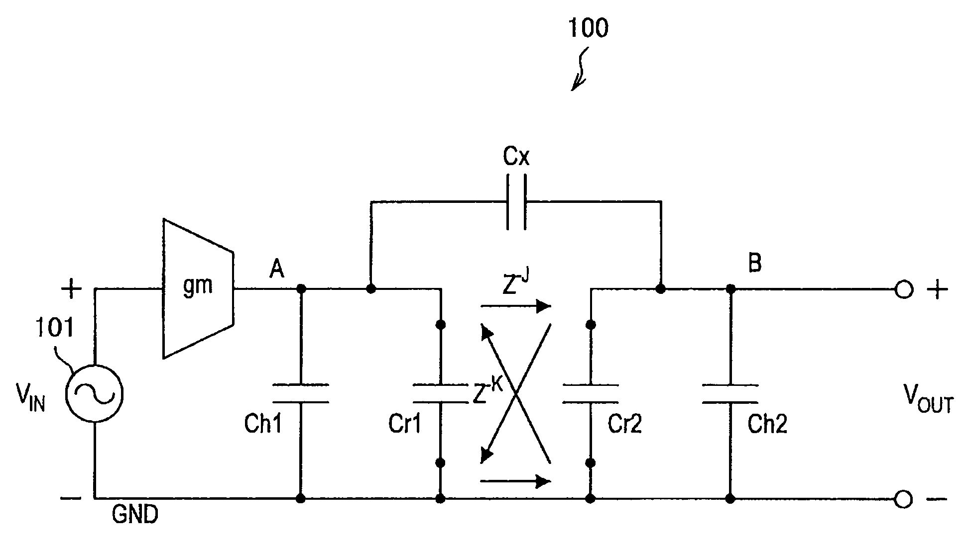
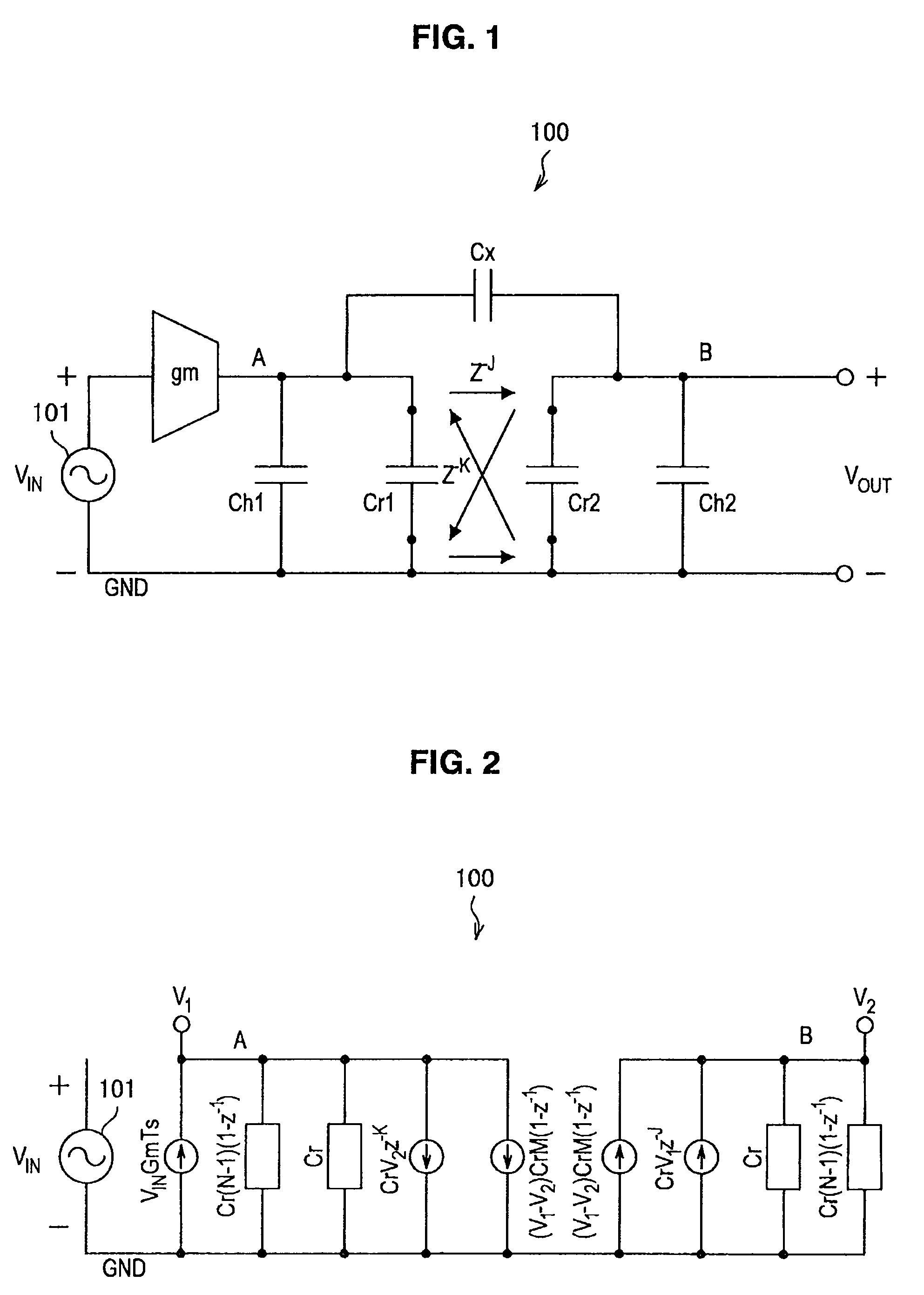
[0010]With the above-described structure, when switching from the input terminal to the output terminal, the flying capacitor maintains polarity, and when switching from the output terminal to the input terminal, the polarity is reversed. The capacitor is provided in parallel with the flying capacitor, between the input terminal and the output terminal of the flying capacitor. As a consequence, owing to the capacitor provided in parallel with the flying capacitor, it is possible to provide the filter circuit having steep attenuation characteristics.
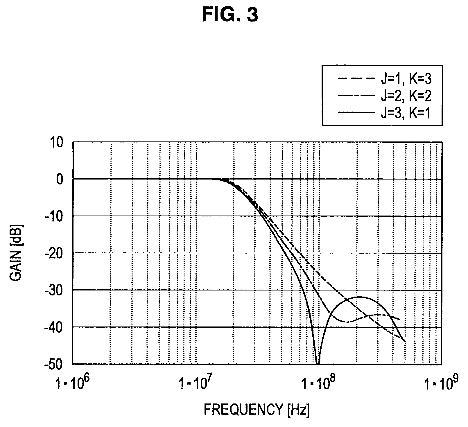
[0017]According to the embodiments of the present invention described above, it is possible to provide a novel and improved filter circuit and communication device capable of having steep attenuation characteristics.

Problems solved by technology

However, with the known charge domain second order IIR-LPF described in “Switched-capacitor lowpass filter without active components,” attenuation characteristics are moderate in the vicinity of the cut-off frequency, and a filter having steep characteristics cannot be structured.

Method used


Image

  • Filter circuit and communication device
  • Filter circuit and communication device
  • Filter circuit and communication device

Examples


Embodiment Construction

)

[0045]Hereinafter, preferred embodiments of the present invention will be described in detail with reference to the appended drawings. Note that, in this specification and the appended drawings, structural elements that have substantially the same function and structure are denoted with the same reference numerals, and repeated explanation of these structural elements is omitted.

[0046]An exemplary embodiment of the present invention will be described in detail in the following order.

[0047]1. Charge domain second order IIR-LPF according to related art

[0048]1-1. Structure of charge domain second order IIR-LPF according to related art

[0049]1-2. Problems of charge domain second order IIR-LPF according to related art

[0050]2. LPF according to embodiment of the present invention

[0051]2-1. Structure of LPF according to embodiment of the present invention

[0052]2-2. Transfer function of LPF according to embodiment of the present invention

[0053]2-3. Frequency characteristics of LPF according ...


PUM


Abstract

There is provided a filter circuit that includes a flying capacitor and a capacitor that is provided in parallel with the flying capacitor, between an input terminal and an output terminal of the flying capacitor. As the capacitor that has a predetermined capacity is provided between the input terminal and the output terminal of the flying capacitor, it is possible to provide steep attenuation characteristics in the filter circuit provided with the flying capacitor.

Description

BACKGROUND OF THE INVENTION[0001]1. Field of the Invention[0002]The present invention relates to a filter circuit and a communication device.[0003]2. Description of the Related Art[0004]The power supply voltage of a radio frequency (RF) circuit tends to decrease along with miniaturization of a complementary metal oxide semiconductor (CMOS) process. Due to the miniaturization of the CMOS process, if an RF circuit is mounted using a known circuit technique, a voltage margin becomes insufficient and the dynamic range of the signal amplitude is narrowed. Meanwhile, the cut-off frequency of a transistor increases due to the miniaturization of the CMOS process, which is advantageous for operations in which high-speed switching operations are performed accurately at a precise timing. In addition, it is also advantageous that the capacitor ratio becomes accurate due to highly accurate lithography.[0005]A digital RF technology is a new technology that introduces the concept of discrete time ...

Claims


Application Information

Patent Timeline
Patent Type & Authority Patents(United States)
IPC IPC(8): H03K5/00
CPCH03H15/00
Inventor IIDA, SACHIOYOSHIZAWA, ATSUSHI
Owner SONY CORP
Learn More