Substrate heat treatment apparatus
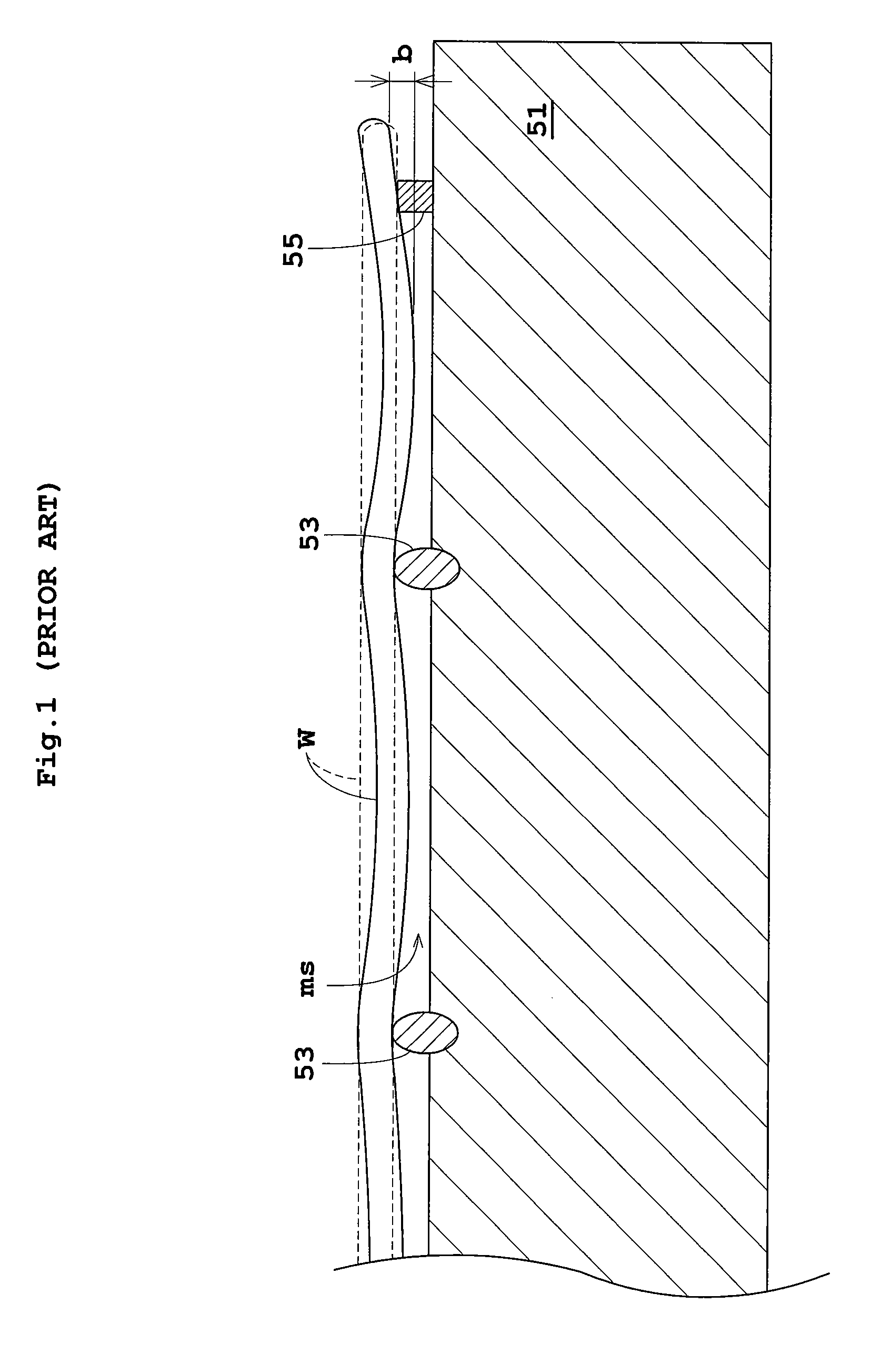
a heat treatment apparatus and substrate technology, applied in lighting and heating apparatus, muffle furnaces, furnaces, etc., can solve problems such as ineffective inhibition of sagging, and achieve the effect of inhibiting sagging of substrates
- Summary
- Abstract
- Description
- Claims
- Application Information
AI Technical Summary
Benefits of technology
Problems solved by technology
Method used
Image

Examples
embodiment 1
[0053]Embodiment 1 of this invention will be described hereinafter with reference to the drawings.
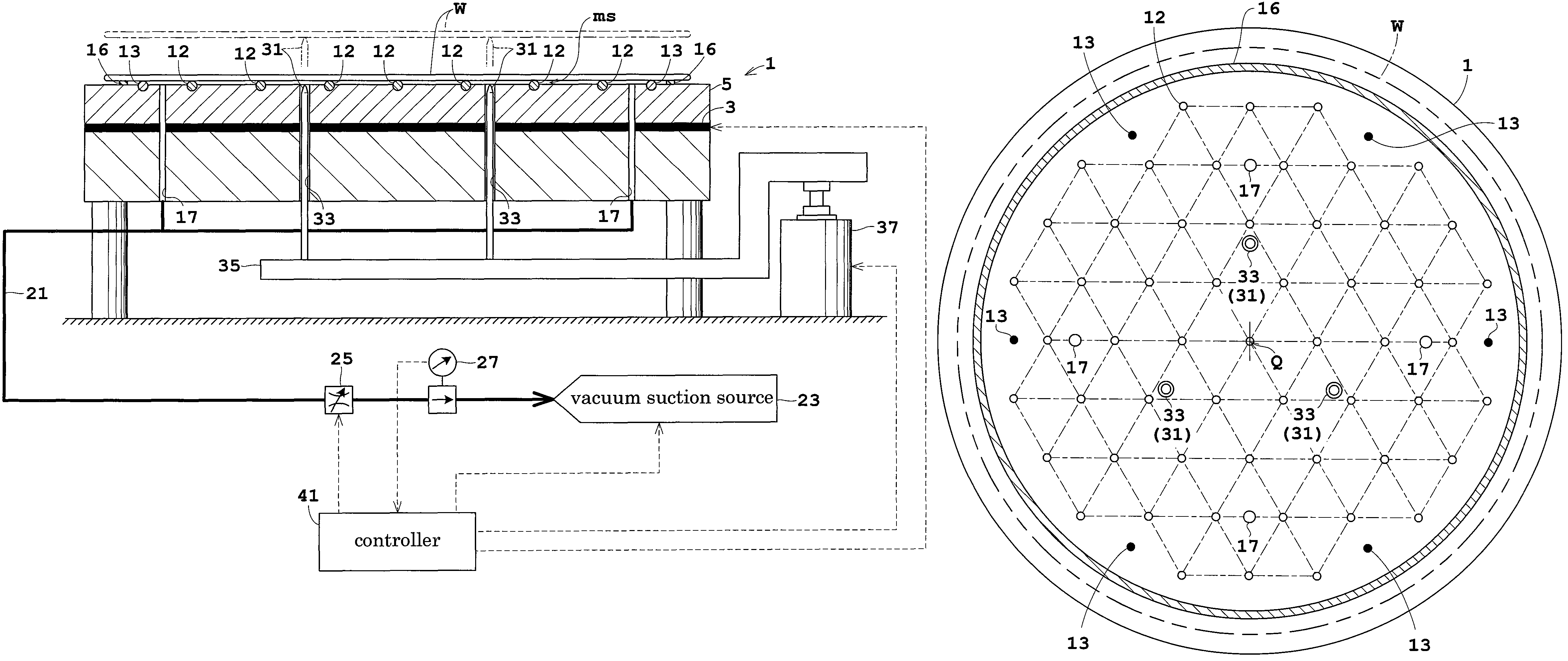
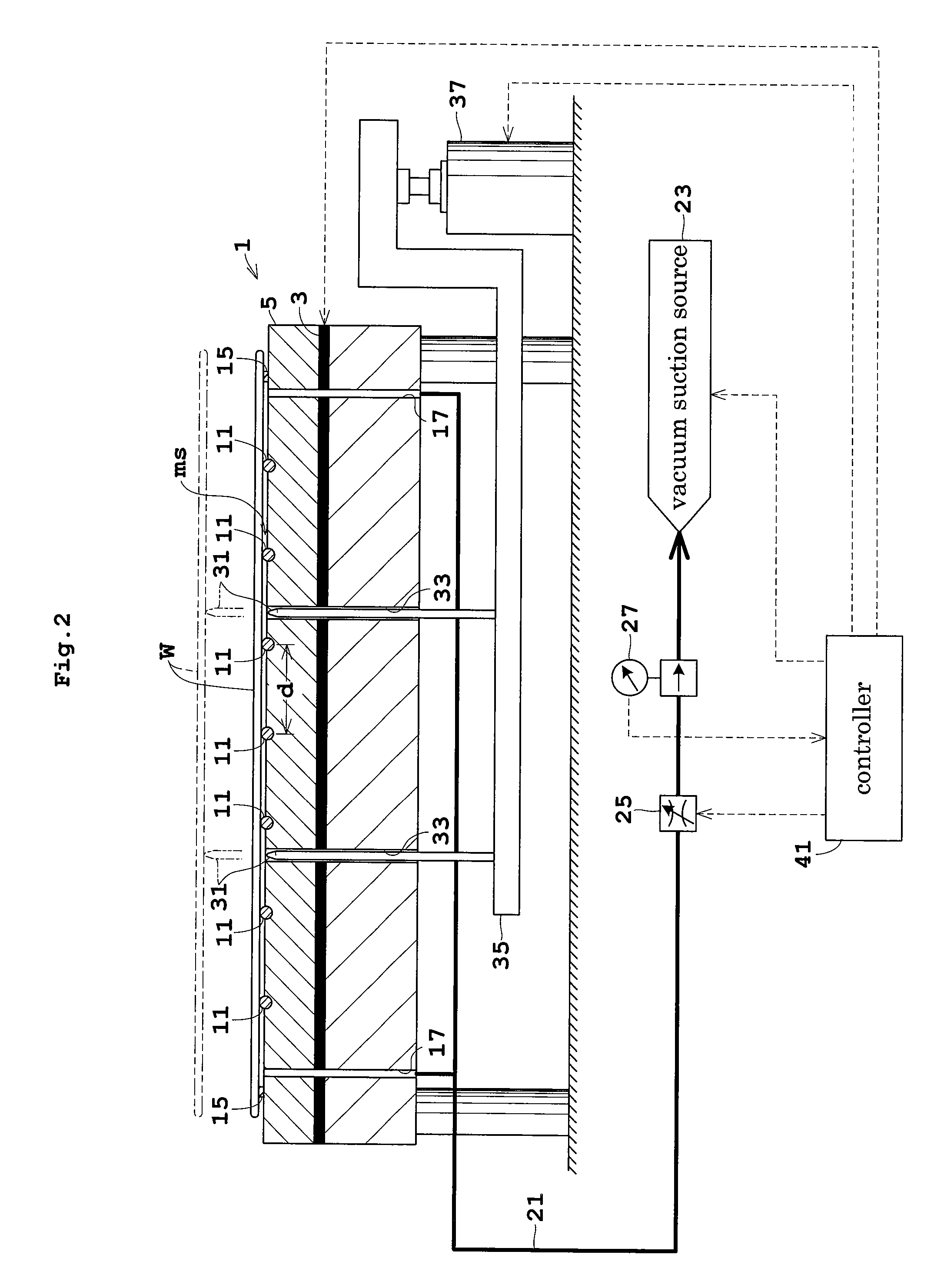
[0054]FIG. 2 is a view in vertical section showing an outline of a substrate heat treatment apparatus in Embodiment 1. FIG. 3 is a plan view of a heat-treating plate.
[0055]A heat-treating plate 1 for supporting a substrate or wafer W under treatment on an upper surface thereof has a heating element 3 such as a mica heater mounted therein. A heat transfer portion 5 between the heating element 3 and the upper surface of heat-treating plate 1 has a plurality of heat pipes, not shown, embedded therein. Cooling grooves, not shown, are formed between the heat pipes for circulating a cooling fluid.
[0056]FIG. 3 refers. The heat-treating plate 1 has a plurality of support elements 11 arranged on the upper surface thereof for contacting and supporting the lower surface of the wafer W. These support elements 11 are located at apexes of equilateral triangles assumed to be arranged regularly and con...
embodiment 2
[0085]Embodiment 2 of this invention will be described hereinafter with reference to the drawings.
[0086]FIG. 9 is a view in vertical section showing an outline of a substrate heat treatment apparatus in Embodiment 2. FIG. 10 is a plan view of a heat-treating plate. Like reference numerals are used to identify like parts which are the same as in Embodiment 1 and will not particularly be described.
[0087]A heat-treating plate 1 has a plurality of first support elements 12 and a plurality of second support elements 13 arranged on the upper surface thereof for contacting and supporting the lower surface of a wafer W. Further, the heat-treating plate 1 has a ring-shaped sealer 16 mounted on the upper surface thereof for contacting positions inward of the edges of the wafer W for rendering gastight a minute space “ms” formed between the wafer W and heat-treating plate 1.
[0088]The sealer 16 is ring-shaped and has an inside diameter slightly smaller than the outside diameter of the wafer W. ...
embodiment 3
[0119]Embodiment 3 of this invention will be described hereinafter with reference to FIG. 15. Like reference numerals are used to identify like parts which are the same as in Embodiment 1 or 2 and will not particularly be described. FIG. 15 is a plan view of a heat-treating plate.
[0120]Embodiment 3 is directed to a substrate heat treatment apparatus having support elements 14, as described below, in place of the first and second support elements 12 and 13 in Embodiment 2. The heat-treating plate 1 has a plurality of (e.g. four) support elements 14 formed on the upper surface thereof for contacting and supporting the lower surface of a wafer W. The support elements 14 are ring-shaped, different in diameter, and arranged concentrically. Grooves 18 are formed in varied positions of each support element 14. Thus, even when the support elements 14 are in contact with the wafer W, the regions inside and outside each support element communicate with each other. The grooves 18 correspond to...
PUM
| Property | Measurement | Unit |
|---|---|---|
| diameter | aaaaa | aaaaa |
| diameter | aaaaa | aaaaa |
| inner pressure | aaaaa | aaaaa |
Abstract
Description
Claims
Application Information
 - R&D
- Intellectual Property
- Life Sciences
- Materials
- Tech Scout
- Unparalleled Data Quality
- Higher Quality Content
- 60% Fewer Hallucinations
Browse by: Latest US Patents, China's latest patents, Technical Efficacy Thesaurus, Application Domain, Technology Topic, Popular Technical Reports.
© 2025 PatSnap. All rights reserved.Legal|Privacy policy|Modern Slavery Act Transparency Statement|Sitemap|About US| Contact US: help@patsnap.com