Multiple cooling sources for a vehicle air conditioning system
a vehicle air conditioning and cooling source technology, applied in refrigeration machines, light and heating equipment, transportation and packaging, etc., can solve the problem of not being able to avoid cost increase, and achieve the effect of reducing the fuel consumption of the engine, and reducing the input energy amoun
- Summary
- Abstract
- Description
- Claims
- Application Information
AI Technical Summary
Benefits of technology
Problems solved by technology
Method used
Image
Examples
first embodiment
An air-conditioning system according to a first embodiment will be explained with reference to the drawings.
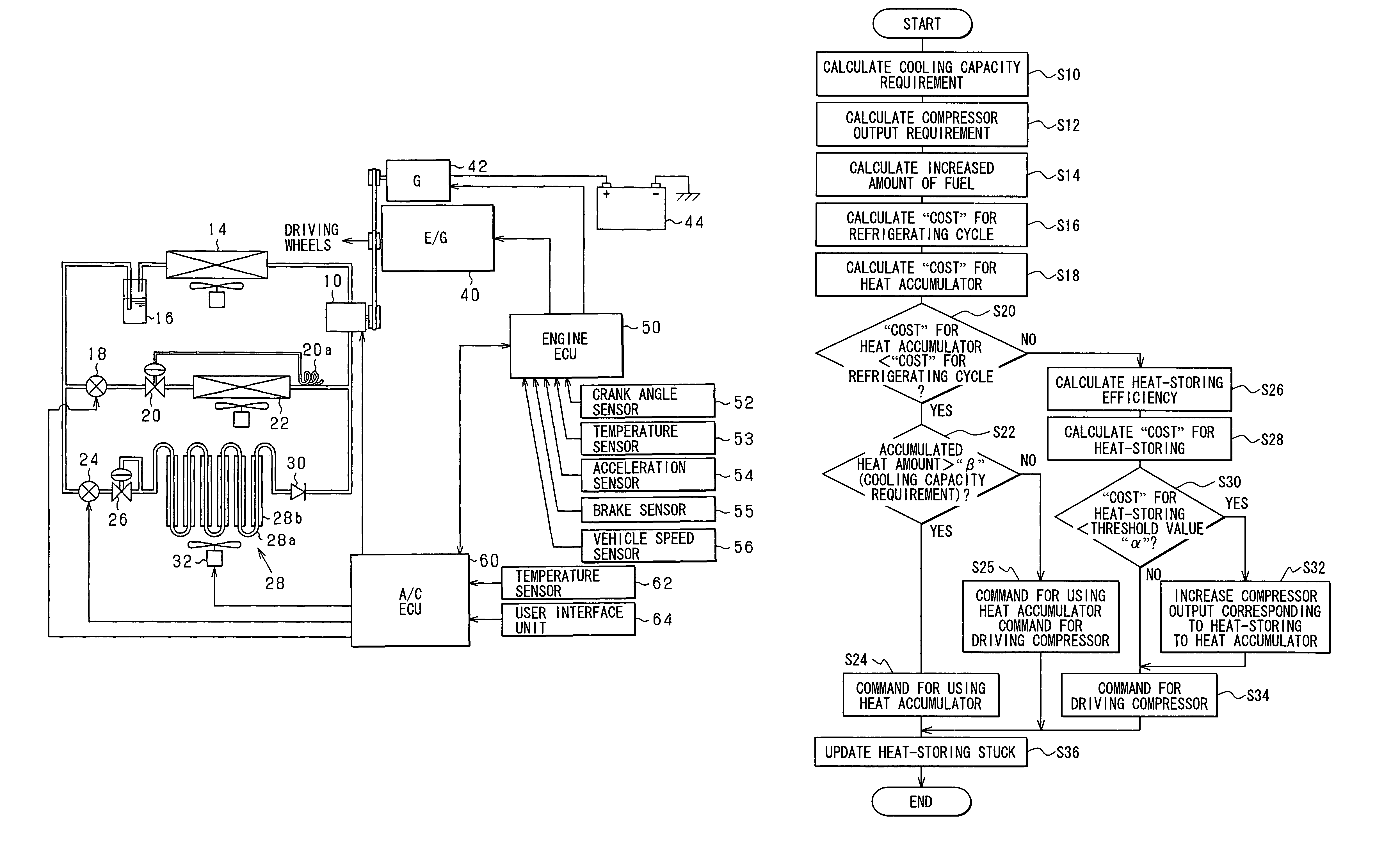
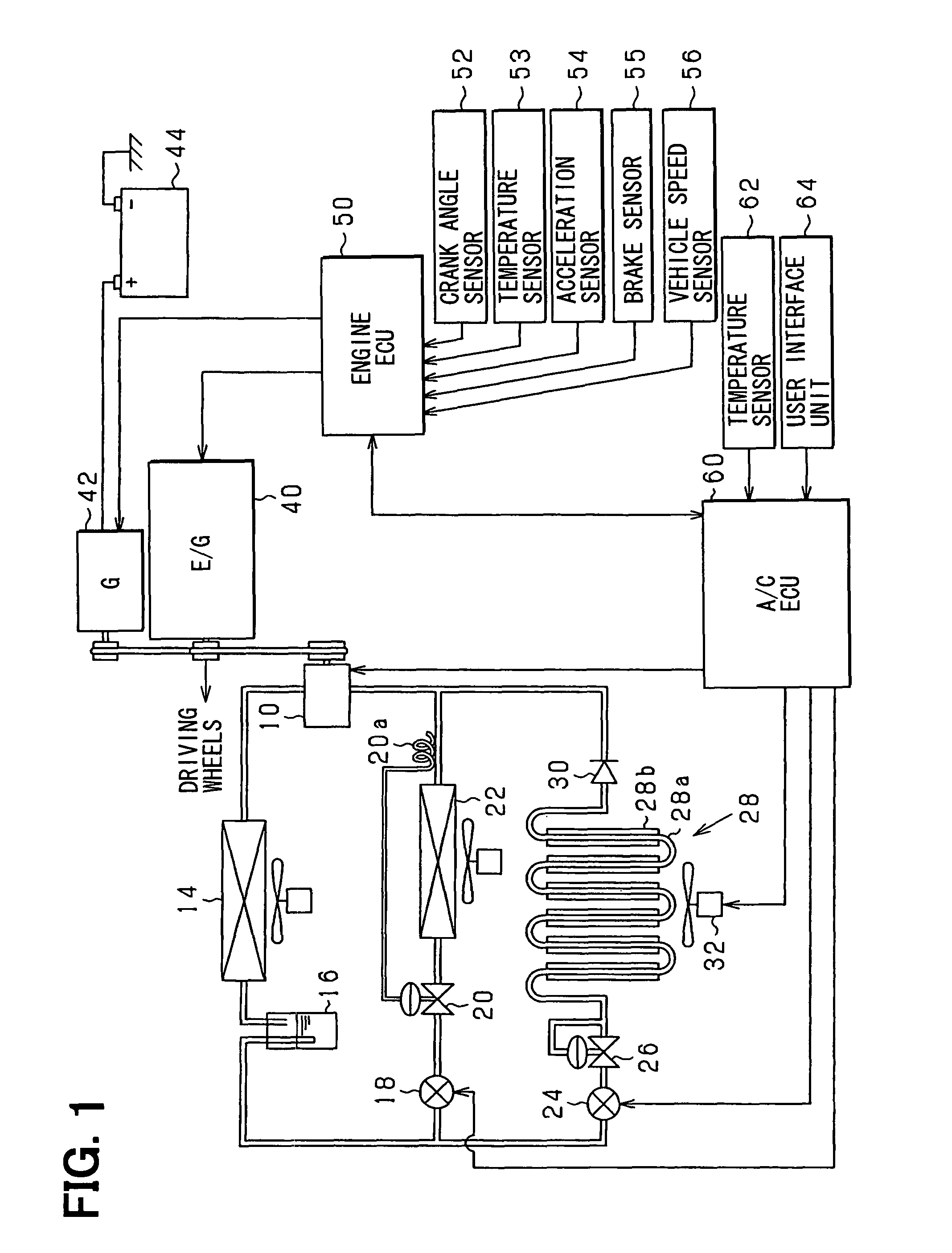
FIG. 1 is a schematic view showing a system structure of an air-conditioning system for a vehicle according to the first embodiment of the present invention.
As shown in FIG. 1, refrigerant is compressed by a capacity variable type compressor 10 and supplied to a condenser 14. The refrigerant is then supplied to a receiver 16 for separating the refrigerant into liquid-phase and gas-phase refrigerant and temporally storing the liquid-phase refrigerant. The refrigerant of the receiver 16 is supplied to an expansion valve 20 of a temperature dependent type through an electromagnetic valve 18. The refrigerant is rapidly expanded by the expansion valve 20, so that the refrigerant is atomized. The atomized refrigerant is vaporized in an evaporator 22 through heat-exchange with outside air. A temperature sensing pipe 20a of the expansion valve 20 is provided at an outlet side of the e...
second embodiment
A second embodiment will be explained with reference to the drawings, by focusing on different points from the first embodiment.
According to the second embodiment, the refrigerating cycle (the evaporator 22) and the heat accumulator 28 are selectively used depending on the operation point of the engine 40, when the temperature of the vehicle inside air is controlled. More exactly, the refrigerating cycle and the heat accumulator 28 are selectively used depending on the rotational speed and the load (the torque) of the engine 40, in accordance with a map shown in FIG. 7.
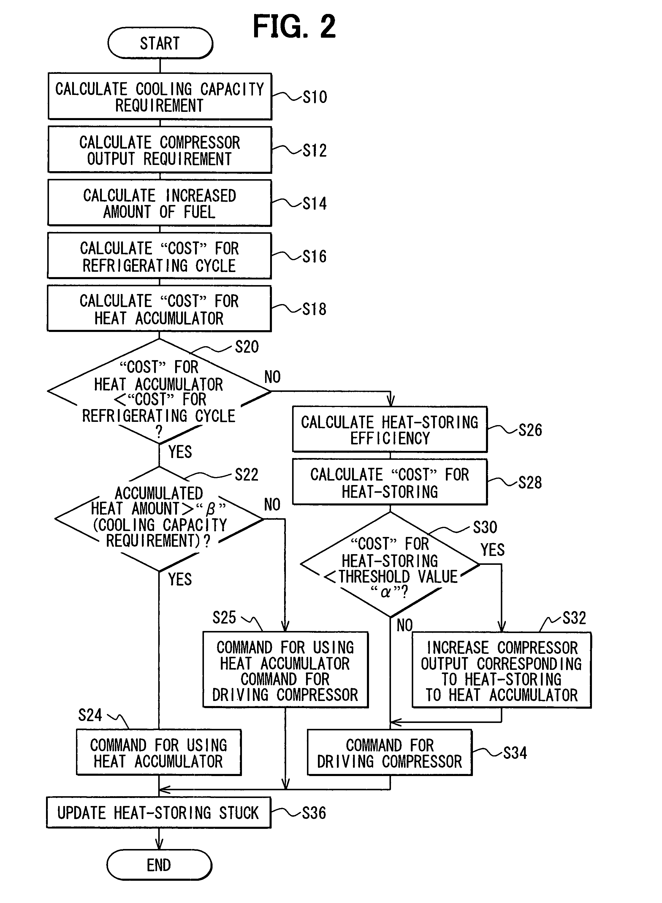
FIG. 8 shows a flowchart for a process of controlling the temperature of the vehicle inside air according to the embodiment. The process of FIG. 8 is repeatedly carried out by the ECU 60 at a predetermined interval.
At first, the ECU 60 determines at a step S40, whether there is a command for cooling the vehicle inside air, based on the operations of the user interface unit 64 and / or the temperature of the vehicle insi...
third embodiment
A third embodiment will be explained with reference to the drawings, by focusing on different points from the first embodiment.
FIG. 9 shows a system structure of an air-conditioning system for a vehicle according to a third embodiment. The same reference numerals are used in the third embodiment for those parts, which are identical or similar to those of the first embodiment (FIG. 1). According to the embodiment, an electric motor 70 is provided as a driving source for driving the compressor 10 in addition to the engine 10 A solar battery 72 is further provided for the purpose of generating the electrical power which will be charged into the battery 44.
FIG. 10 shows a flowchart for a process of controlling the temperature of the vehicle inside air according to the embodiment. The process of FIG. 10 is repeatedly carried out by the ECU 60 at a predetermined interval.
At steps S50 to S56, the ECU 60 carries out the same processes to the steps S10 to S16 of FIG. 2. However, at the step ...
PUM
 Abstract
Description
Claims
Application Information
 - R&D
- Intellectual Property
- Life Sciences
- Materials
- Tech Scout
- Unparalleled Data Quality
- Higher Quality Content
- 60% Fewer Hallucinations
Browse by: Latest US Patents, China's latest patents, Technical Efficacy Thesaurus, Application Domain, Technology Topic, Popular Technical Reports.
© 2025 PatSnap. All rights reserved.Legal|Privacy policy|Modern Slavery Act Transparency Statement|Sitemap|About US| Contact US: help@patsnap.com


