Multimode voltage regulator circuit

Active Publication Date: 2011-08-02
TELEFON AB LM ERICSSON (PUBL)
View PDF7 Cites 39 Cited by
  • Summary
  • Abstract
  • Description
  • Claims
  • Application Information

AI Technical Summary

Benefits of technology

Combining a switching regulator, for use when a required load current is high, with a linear regulator, for use when the load current is low, results in higher efficiency for all load currents than can be achieved by either the switching regulator or linear regulator alone. The disclosed multimode voltage regulators may be especially attractive for use in devices such as mobile phones, in which long periods of very low current use are interspersed with periods of high current use. In certain embodiments, a switching regulator can be modified to form a multimode voltage regulator with only a few additional components.
In some embodiments, the multimode voltage regulator circuit is implemented as a monolithic integrated circuit, perhaps requiring an external inductor and / or external filter capacitor, while in others the regulator circuit is implemented with discrete devices or a combination of discrete devices and one or more integrated circuits. In some embodiments, the linear regulator sub-circuit and the switching regulator sub-circuit share a transistor, so that the shared transistor operates as a variable-resistance pass transistor in the low-current mode and as a low-on-resistance switching transistor in the high-current mode. Sharing components, such as the error amplifier and the shared transistor, between the low-current and high-current operating modes reduces the size and / or cost of the multimode regulator circuit.

Problems solved by technology

Those skilled in the art are aware that linear regulators are inherently inefficient at high load currents because of the resistive voltage drop across the pass device.
Buck regulators, on the other hand, can be much more efficient than linear regulators at high load currents, but tend to be inefficient at low load currents.
The low-current efficiency of buck regulators (and switching regulators in general) is limited by losses in the switching and rectifier transistors, and because the control circuitry is more complex and consumes more power than that of a linear regulator.
Given such a wide range of load current, a linear regulator will be less efficient than a buck regulator when the regulator's output current is high, while a buck regulator will be less efficient than a linear regulator during the long periods when the phone is powered on but inactive.

Method used


Image

  • Multimode voltage regulator circuit
  • Multimode voltage regulator circuit
  • Multimode voltage regulator circuit

Examples


Embodiment Construction

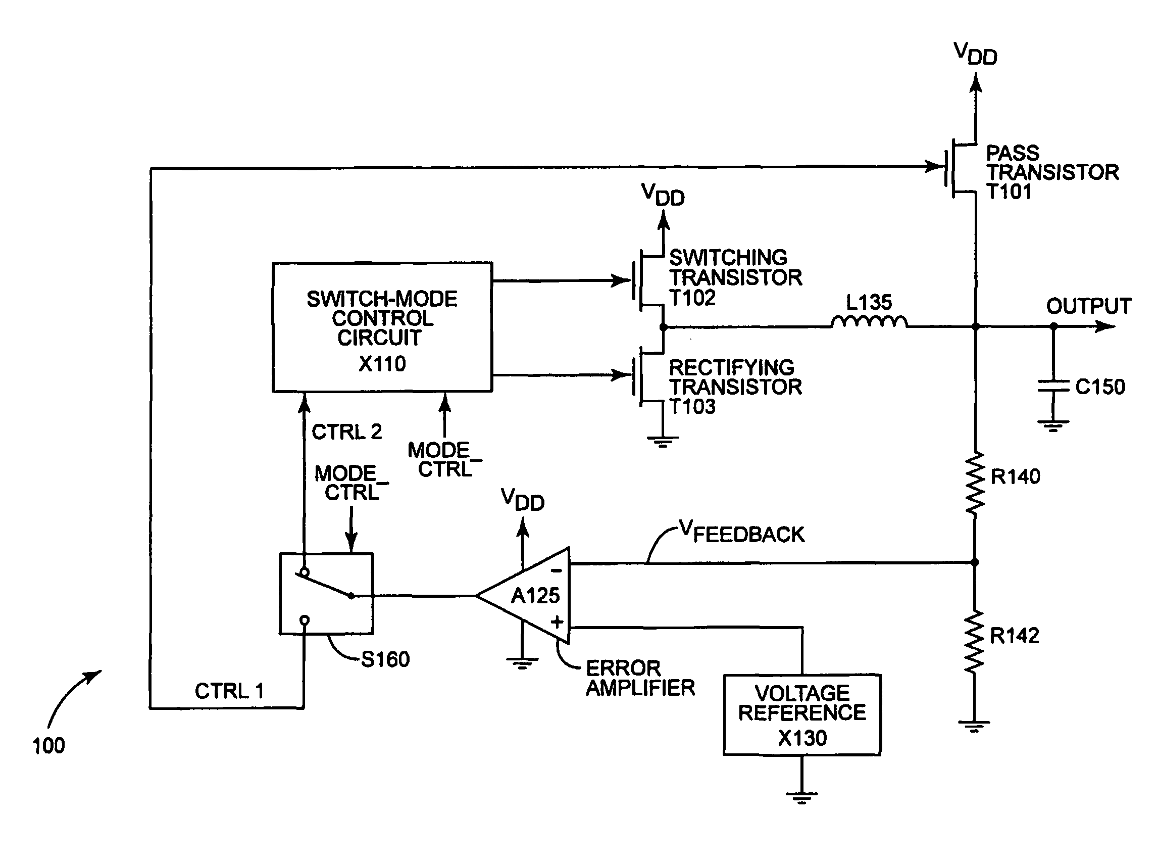
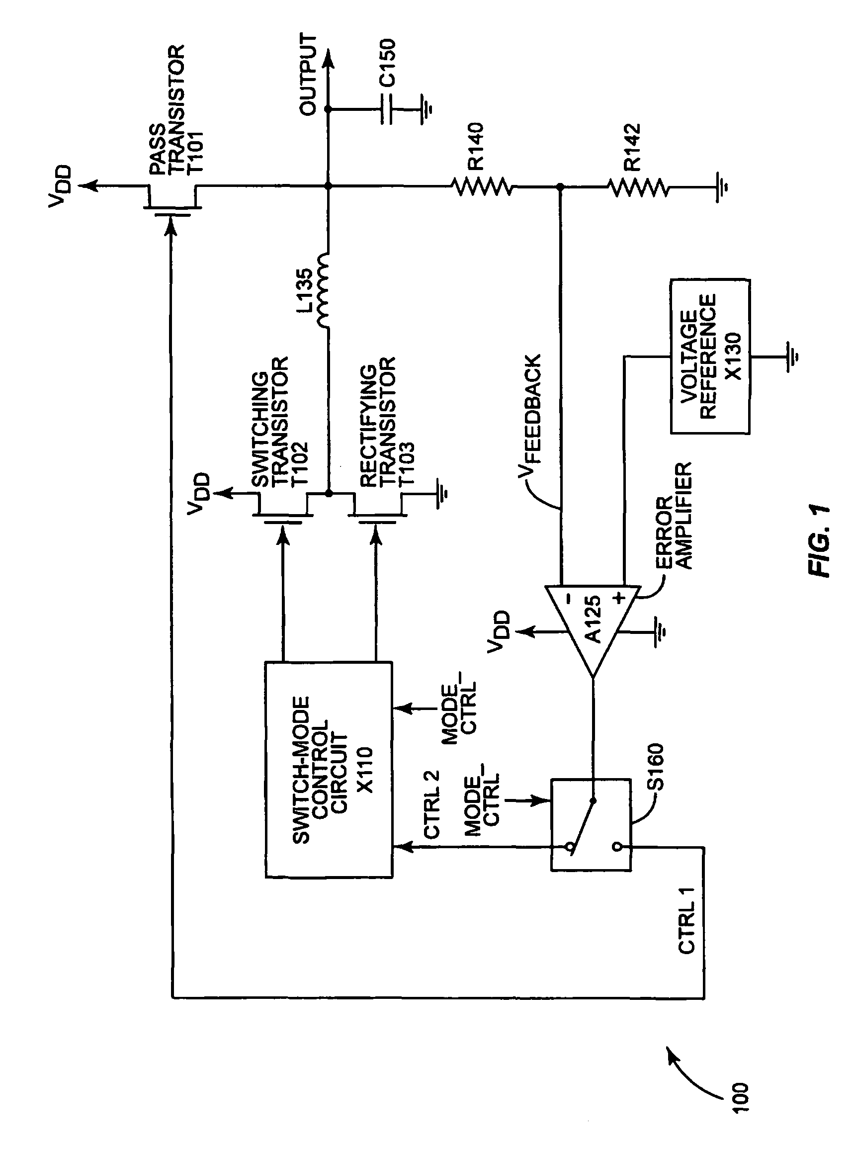
FIG. 1 illustrates an exemplary multimode voltage regulator circuit 100 according to some embodiments of the present invention. Multimode voltage regulator circuit 100 includes a linear regulator sub-circuit, which comprises pass transistor T101, configured to supply current from supply VDD to a load (at “OUTPUT”), under the control of a control signal CTRL1. As is well known to those skilled in the art, pass transistor T101 can be operated in its linear (or “ohmic”) region as a variable-resistance device, thus effectively creating a voltage divider between the supply voltage VDD and ground, through the load. If the control signal CTRL1 is an error signal derived by comparing the output voltage to a reference voltage, as shown in FIG. 1, then the resistance of pass transistor T101 is continuously adjusted to maintain a substantially constant voltage at the load, despite changes in the load's current requirements or changes in the supply voltage VDD. Capacitor C150, which in some emb...


PUM


Abstract

A multimode voltage regulator circuit includes a linear regulator sub-circuit configured to supply current to a load in a low-current mode, responsive to a first control signal from a first control path, as well as a switching regulator sub-circuit configured to supply current to the load in a high-current mode, responsive to a second control signal from a second control path. The circuit further comprises a shared error amplifier configured to generate an error signal based on the difference between a reference voltage and a feedback signal coupled from the load, and a switch configured to selectively route the error signal to the first control path in the low-current mode and to the second control path in the high-current mode.

Description

The present invention generally relates to voltage regulator circuits and particularly relates to a multimode voltage regulator having low-current and high-current modes.BACKGROUNDVoltage regulators are used to convert a supply voltage from one value to a different value, frequently from a high voltage to a lower voltage. In some applications, voltage regulators are used to provide current to a load at a stable voltage, despite a varying supply voltage, such as from a battery. In other applications, a voltage regulator may be used primarily for converting an input supply voltage to an operating voltage that is more convenient or more efficient for a particular circuit. In some applications, both of these functions may be important. For example, the battery voltage in some mobile phones is nominally 3.6 volts, but varies considerably as the battery discharges. Some of the integrated circuits within the mobile phone are designed to operate at voltages as low as 1.0 volts, to minimize ...

Claims


Application Information

Patent Timeline
IPC IPC(8): G05F1/40
CPCH02M3/156
Inventor PETTY, JOHN STEWART
Owner TELEFON AB LM ERICSSON (PUBL)
Why Eureka
Try Eureka