Metal foil resistor

a metal foil and resistor technology, applied in resistors, resistor details, electrical devices, etc., can solve problems such as metal foil strain or distortion, and achieve the effects of reducing the number of control factors, preventing any strain or distortion of metal foil, and facilitating design

Active Publication Date: 2011-07-19
ALPHA ELECTRONICS
View PDF21 Cites 3 Cited by
  • Summary
  • Abstract
  • Description
  • Claims
  • Application Information

AI Technical Summary

Benefits of technology

[0011]The metal foil resistive element is contained in the package in the insulated state so as to be expandable and contractible in the extending direction (planar direction) of the metal foil. When the metal foil is positioned along the horizontal direction, geographic vertical direction and tilt direction of the package, the planner direction of the metal foil is along the horizontal, geographic vertical and tilt directions, respectively. The metal foil is not fixed on the substrate by an adhesive or cement. Therefore, even when the package temperature or metal foil temperature changes owing to the change of the ambient temperature or self-heating of the metal foil, the metal foil itself can freely expand and contract in its extending direction since any stresses are not induced and not applied to the metal foil. Any strain or distortion of the metal foil is prevented. With such arrangement, by using the metal foil having a sufficiently small TCR which can be achieved by appropriate alloy composition adjustment, rolling process, heat treatment and / or etching process, the TCR of the resistor can sufficiently be reduced and stabilized.
[0012]Moreover, unlike the conventional resistor unit, it is not necessary to consider the change of the TCR due to control factors such as the materials, the thicknesses and the structures of the substrate, the adhesive or cement, the package and the like. Therefore, the number of control factors are reduced, design is facilitated, and the degree of freedom of design increases.
[0013]Furthermore, the external stress to be applied to the package is not directly transmitted to the metal foil. Therefore, even when the package is fixed so as to come into close contact with the appropriate heat sink, the TCR might not be adversely affected.

Problems solved by technology

Due to the differential thermal expansion coefficients, a stress is applied to the metal foil by a change of an ambient temperature and self-heating of the metal foil resistor, and thereby the metal foil is strained or distorted.

Method used


Image

  • Metal foil resistor
  • Metal foil resistor
  • Metal foil resistor

Examples


first embodiment

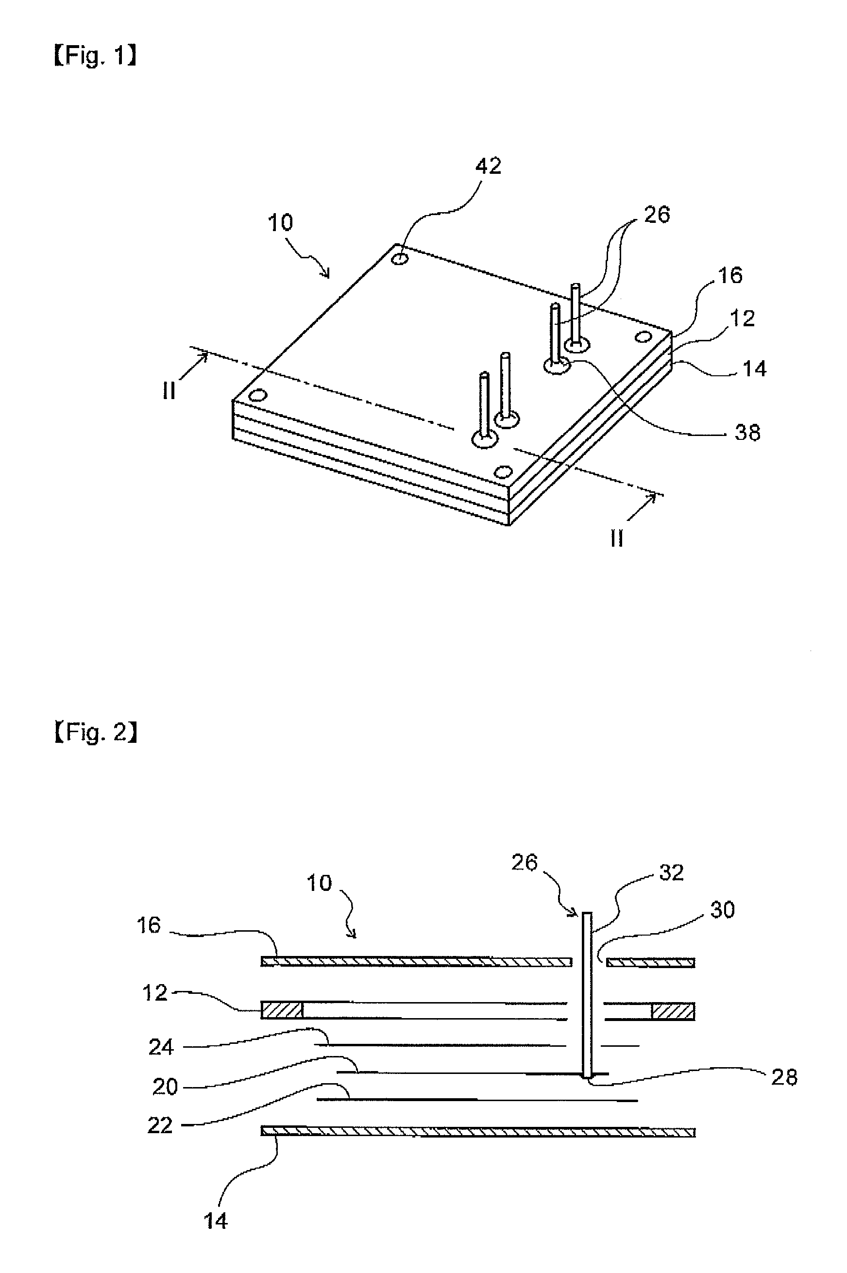
[0053]The present invention will be described hereinafter in detail in accordance with a standard resistor to which one embodiment of the present invention has been applied with reference to FIGS. 1 to 4.

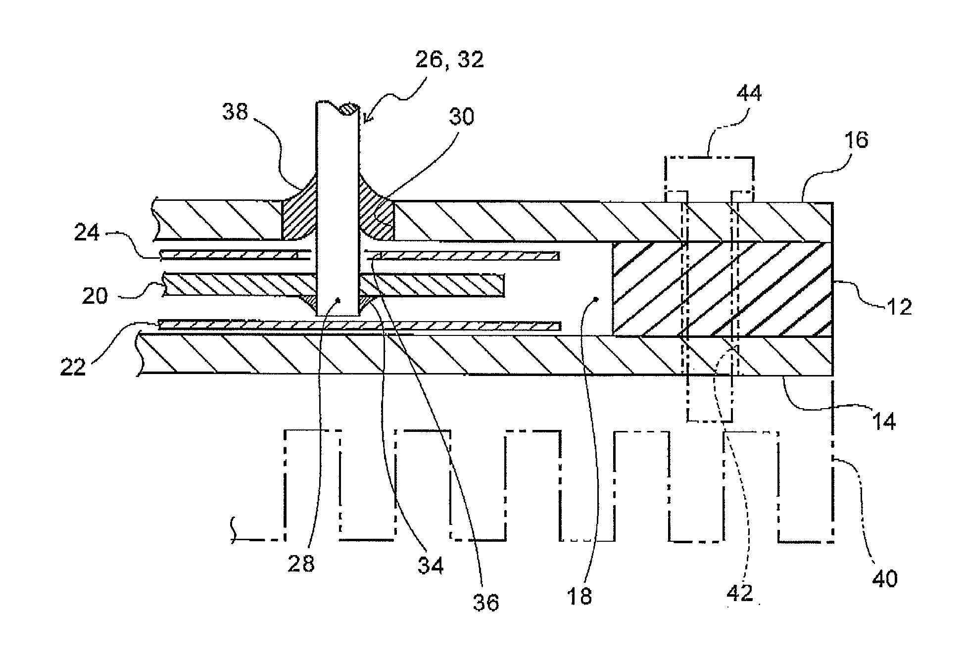
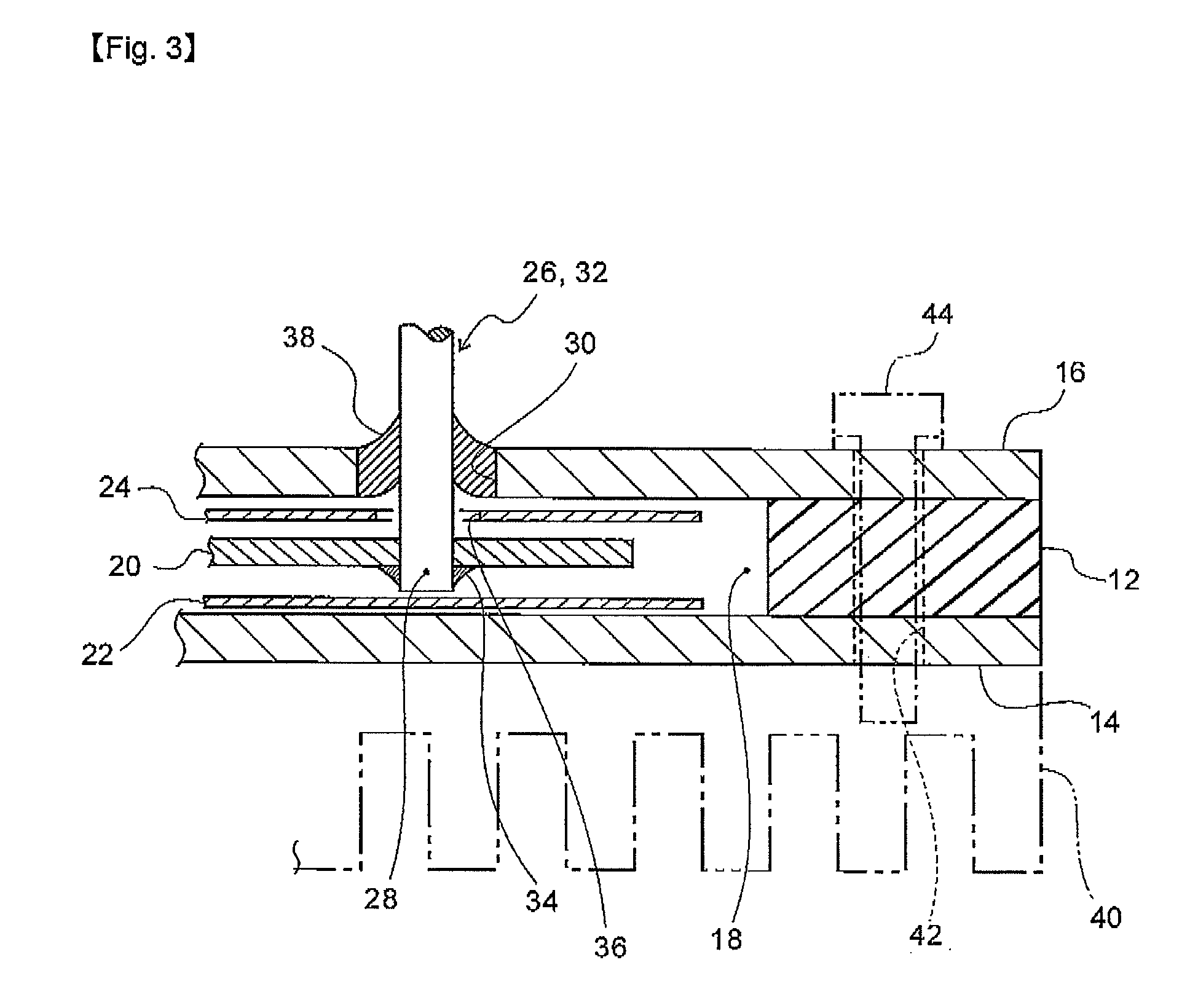
[0054]In these figures, reference numeral 10 is a package made of a metal and constituted by superimposing a quadrangular frame 12 on a bottom cover 14 and a top cover 16 so that they are brought into close contact with each other and fixed. Accordingly, in the package 10, there is formed a flattened space having a height equal to a thickness of the frame 12, which serves as a resistor accommodation space or chamber 18 (FIG. 3).

[0055]This package 10 contains a metal foil resistive element 20 constituted of a metal foil in which a resistance circuit pattern is formed and which is electrically insulated from the package 10. In this embodiment, insulator films 22, 24 are superimposed on opposite surfaces of the metal foil resistive element 20, and installed in the resistor accommodatio...

second embodiment

[0066]FIG. 5 is an exploded enlarged sectional view of the vicinity of a relay terminal connecting portion in another embodiment. In this embodiment, a relay terminal insertion hole 30A is formed in a frame 12A of a package 10A in a horizontal direction (direction perpendicular to a thickness direction). After a relay terminal 26A is passed through the insertion hole 30A, the insertion hole 30A is sealed with a resin or glass. A flat inner end 28A of the relay terminal 26A is superimposed on and connected to an electrode of a metal foil resistor 20A.

[0067]This resistive element 20A and the inner end 28A are sandwiched between the insulator films 22A and 24A, and a bottom cover 14A and a top cover 16A are overlaid on the frame 12A to hermetically seal the resistive element 20A and the inner end 28A.

third embodiment

[0068]FIG. 6 is a sectional view of the vicinity of a relay terminal connecting portion in still another embodiment, and FIG. 7 is an exploded view of FIG. 6. In a package 10B of this embodiment, one end 14B′ of a bottom cover 14B is protruded outwardly from a frame 12B. And conductive pads 50, 52 are formed on the surface of the protruded portion 14B′ and in a resistor accommodation space 18B positioned inside of the frame 12B, respectively. These pads 50, 52 are connected to each other by an inner layered circuit 54 of the bottom cover 14B. The conductive pads 50, 52 and the inner layered circuit 54 can be prepared in a technique similar to that of a known printed wiring board.

[0069]A metal foil resistive element 20B is soldered to the conductive pad 52. In this soldering, for example, solder plating, solder ball, solder paste or the like may be supplied to the surface of the conductive pad 52 beforehand, and an electrode of the resistive element 20B may be pressed and heated on t...


PUM


Abstract

The metal foil resistor having a metal foil resistive element 20 composed of a metal foil whereupon a resistance circuit pattern is formed. The metal foil resistor comprises: a package 10 which contains the metal foil resistive element 20 in an electrically insulated state so that the resistive element can be expandable and contractible in a spreading direction of the metal foil; and a relay terminal 26 which is held in the package 10 in the electrically insulated state and is connected to an electrode 20a of the metal foil resistive element 20. A temperature coefficient of resistance can be reduced and stabilized. Control factors can be reduced to increase degrees in freedom in designing. Further, an external stress applied to a package is prevented from transmitting to the metal foil resistive element, and therefore the package can be easily attached to a discretionary heat sink.

Description

TECHNICAL FIELD[0001]The present invention relates to a metal foil resistor in which a metal foil resistive element constituted of a metal foil provided with a resistance circuit pattern is encapsulated in a package, and an electrode of the metal foil resistive element is connected to an outer relay terminal.BACKGROUND ART[0002]There is known a metal foil resistor in which a resistance circuit pattern is formed in a metal foil attached to an insulating substrate with an adhesive, and this whole substrate is encapsulated with a resin coating. In this type of resistor, it is necessary to reduce a change of a resistance value with respect to a temperature change as much as possible, that is, reduce a temperature coefficient of resistance (hereinafter referred to as TCR).[0003]An increase of the TCR is mainly due to the difference of the thermal expansion coefficient between the metal foil and the substrate to which the foil has been bonded or the difference of the thermal coefficient b...

Claims


Application Information

Patent Timeline
Patent Type & Authority Patents(United States)
IPC IPC(8): H01C7/06
CPCH01C1/016H01C1/08H01C3/06H01C7/06
Inventor ZAMA, MATSUOOKAMOTO, TORU
Owner ALPHA ELECTRONICS
Why Eureka
Try Eureka