Rectification apparatus using a heat pump

a technology of rectifying apparatus and heat pump, which is applied in the direction of lighting and heating apparatus, liquid degasification, separation process, etc., can solve the problems of clogging the liquid passage, remanent evaporation of the entire body, and plate-type heat exchangers, etc., and achieves small pressure differential, high ammonia concentration, and low power consumption

Inactive Publication Date: 2011-07-05
HOLM CHRISTENSEN BIOSYSTEMER APS
View PDF15 Cites 9 Cited by
  • Summary
  • Abstract
  • Description
  • Claims
  • Application Information

AI Technical Summary

Benefits of technology

[0006]The system with atomizing rotor throwing the liquid against a heat transmission surface provides several advantages. The rotor may be designed as described in EP 1 185 346 B1, i.e. constructed with a central tube-shaped supporting mid-section provided with a suitable number of U-shaped pockets welded thereto, said pockets being open in the direction of rotation of the rotor. At the bottom of the container, the outer edges of the pockets dip a few millimetres into the liquid, said pockets thus collecting liquid which is thrown outward by centrifugal forces during continued rotation, said liquid forming a concentrated cloud of small droplets from the edges of the pockets towards the inner side of the housing wall and impacting on the surface of the heat transmission surface. The cloud rotates with the speed of the atomizing rotor, while the droplets are thrown outward with a velocity of approx. 10 m / s, thus a relative difference in velocity between liquid and vapour of an average up to 30 m / s is obtained, thus resulting in an effective contact between liquid and vapour, whereby an equilibrium between the easily vaporizable portion in the liquid and in the vapour is obtained for each recirculation.
[0032]After having passed the scrubber, the liquid mixture is refluxed to the apparatus for decomposition of ammonium bicarbonate into CO2 gas and ammonia, and since scrubbing can be carried out with a considerably higher ammonia concentration in the scrubbing liquid than in the liquid manure, stripping alone, or perhaps a very modest reflux, is sufficient, and the heat pump can thus operate with a small pressure differential and a low power consumption. A theoretical power consumption of 15 kW alone for the heat pump for removing 1 metric ton of CO2 gas with adiabatic compression is achievable, and it appears that this system satisfies a need even with a modest pump efficiency.

Problems solved by technology

The apparatus is usable for many different mixtures, the focus, however, being directed towards aqueous mixtures containing ethanol or ammonia, where mixtures of ammonia and water are particularly difficult to treat, since in the latter case, the difference in boiling points is approx.
Rectification plants still use evaporators containing pipes as heat transfer surfaces, said evaporators being designed as down draught evaporators or as recirculation evaporators, the greatest disadvantage of the method being that the entire evaporation takes place with a remanence that has obtained its final concentration.
The same disadvantage is mentioned in connection with the plate-type heat exchangers having found a certain use recently.
The stripping section of a conventional column with bell-shaped bottoms, sieve bottoms or contact inserts of different types may become clogged, since there is a large quantity of dry matter capable of forming encrustations, which again can fall off, thus clogging the liquid passage.
In connection with such systems, it may be necessary to start with decantation or filtration, which may be expensive to carry out, and the removed dry matter will not be stripped.

Method used


Image

  • Rectification apparatus using a heat pump
  • Rectification apparatus using a heat pump
  • Rectification apparatus using a heat pump

Examples


Embodiment Construction

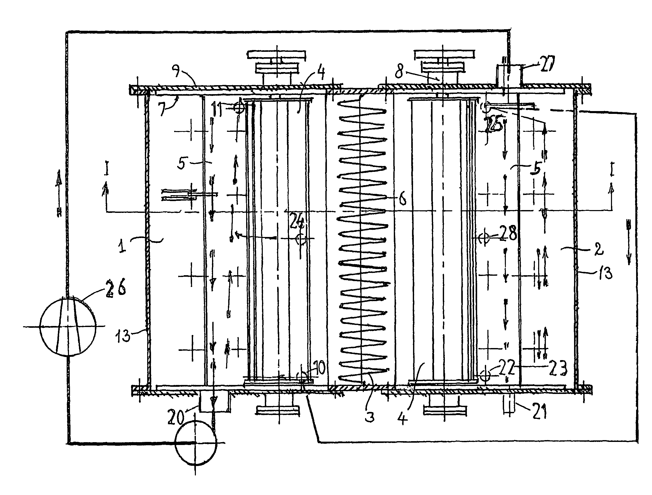
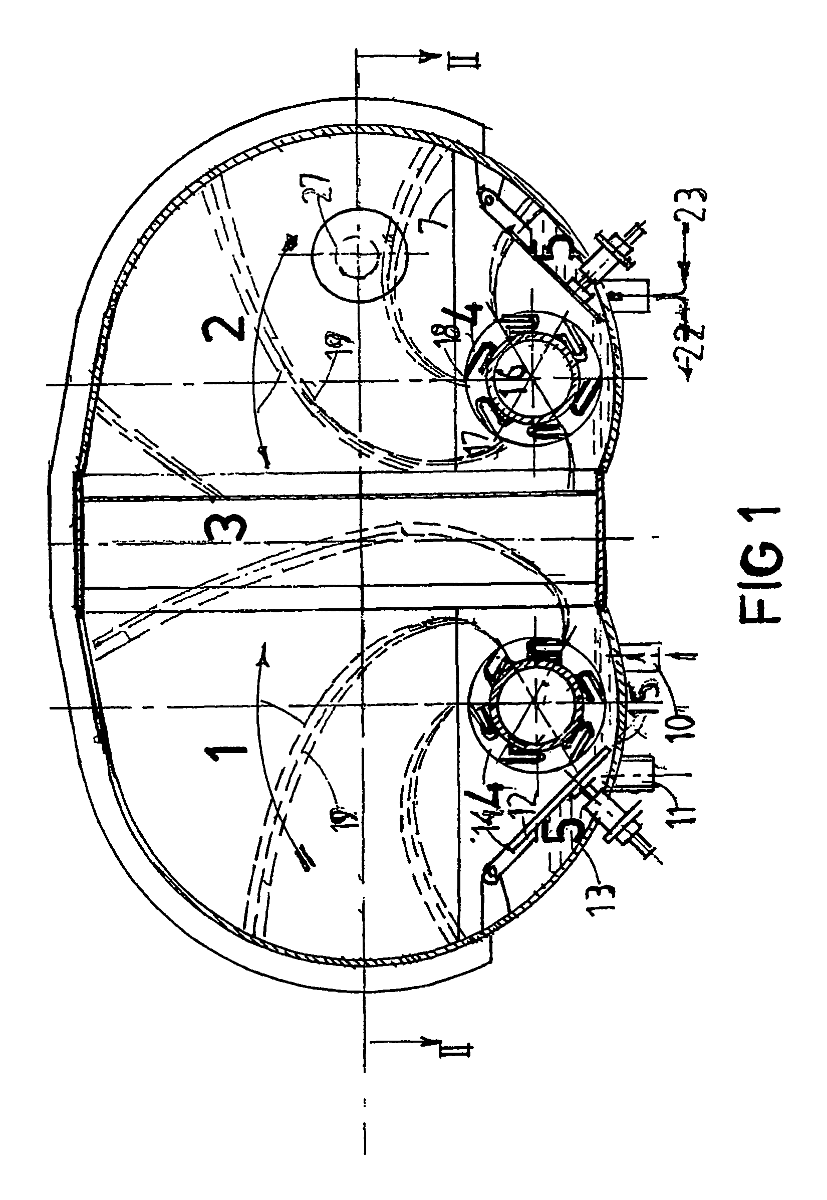
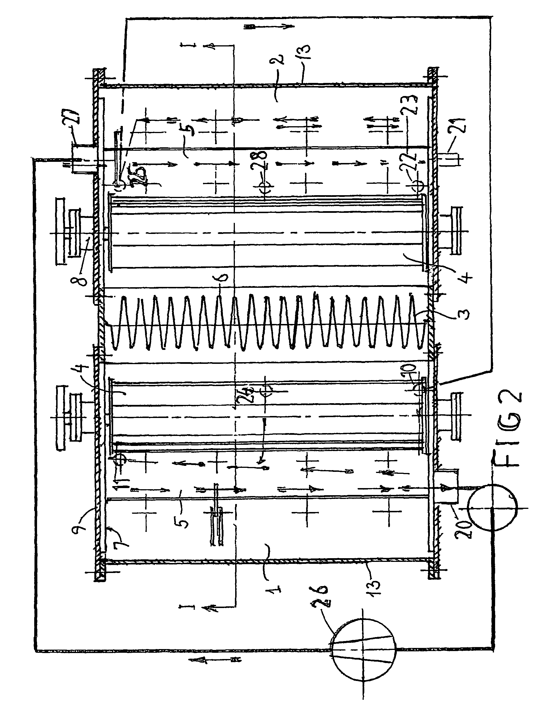
[0036]FIGS. 1 and 2 show a cross-section of the apparatus comprised of a stripping and strengthening section 1 and a condensing and final strengthening section 2 as well as a common heat transmission body 3 separating the two sections by constituting the common wall between the two sections. The remainder of the housing walls are preferably partially cylindrical walls 13 and end walls provided with a fixed part 7 for mounting of atomizing rotor bearings 8, while a remaining opening in the end walls is closed by means of removable covers 9 provided with various connections for liquid and vapour and simultaneously acting as a manhole cover. In principle, the components of the two sections are per se known and identical, their function, however, differs. Each section is provided with an atomizing rotor 4 and an axial liquid channel 5, the function of which is partly to control the inflow of liquid to the atomizing rotor 4 and partly to ensure axial transport of the liquid mixture throu...


PUM

PropertyMeasurementUnit
velocityaaaaaaaaaa
velocityaaaaaaaaaa
boiling pointaaaaaaaaaa

Abstract

An apparatus for stripping and strengthening and subsequent condensing and final strengthening of an easily vaporizable component of a preferably aqueous mixture permits the heat necessary for stripping and strengthening to be transferred through a common heat transmission body (3), where the heat is derived from condensing the vapor generated by stripping and strengthening, which vapor via compression using a heat pump (26) has obtained the increase in boiling point necessary for condensation. The apparatus is comprised of two sections, namely a stripping and strengthening section or first section (1) and a condensing and final strengthening section or second section (2), said sections being joined around a common heat transmission body (3) forming a dividing wall, each section being further defined by a horizontal partially cylindrical housing (13) and an end wall at each end. Each of the sections is provided with an atomizing rotor (4) adapted to throw liquid from each side from the bottom of the horizontal partially cylindrical housing (13) inward against the common heat transmission body, an axial liquid channel (5) providing a continuous passage of liquid through the apparatus extending along the bottom.

Description

TECHNICAL FIELD[0001]The invention relates to an apparatus for stripping and strengthening and a subsequent condensing and final strengthening of an easily vaporizable component of a preferably aqueous mixture, wherein the heat necessary for stripping and strengthening is transferred through a common heat transmission body. The heat stems from condensing the vapour generated by stripping and strengthening, which vapour via compression using a heat pump has obtained the increase in boiling point necessary for condensation.DISCLOSURE OF INVENTION[0002]According to the invention the apparatus is comprised of two sections, namely a stripping and strengthening section or first section and a condensing and final strengthening section or second section, said sections being joined around a common heat transmission body forming a dividing wall, and each section being further defined by a substantially horizontal partially cylindrical housing and an end wall at each end, and where each of sai...

Claims


Application Information

Patent Timeline
Patent Type & Authority Patents(United States)
IPC IPC(8): B01D19/00
CPCB01D1/16B01D1/28B01D3/007B01D5/0015B01D3/002Y02B30/52
Inventor JENSEN, ERIK
Owner HOLM CHRISTENSEN BIOSYSTEMER APS
Why Eureka
Try Eureka