
Energetic thin-film based reactive fragmentation weapons

a thin film, reactive fragment technology, applied in the direction of explosives, weaving, looms, etc., can solve the problems of general lack of confidence in the ignition of such reactive fragments, certain engineering challenges, and the improvement of the lethality of the munition, so as to reduce the impact velocity and improve the effect of tailoring the energy reactive behavior

Active Publication Date: 2011-06-07
LOCKHEED MARTIN CORP
View PDF22 Cites 11 Cited by
  • Summary
  • Abstract
  • Description
  • Claims
  • Application Information

AI Technical Summary

Benefits of technology

The present invention provides a munition with a reactive fragment that has improved energy reactive behavior. This can reduce the impact velocity required to initiate an energetic reaction. The reactive fragment comprises a thin layered structure made of at least one layer of reducing metal and at least one layer of metal oxide. This structure is combined with a binder material to form a mixture, which is then shaped to form the reactive fragment. The technical effect is a more efficient and tailorable energy reactive behavior in the munition.

Problems solved by technology

Upon impact with the target reactive fragments release additional chemical or thermal energy thereby enhancing damage, and potentially improving the lethality of the munition.
However, certain engineering challenges are often encountered in the development of such reactive fragments.
There has been a general lack of confidence in the ignition of such reactive fragments upon impact at velocities less than about 4000 ft / s.
Thus, such conventionally constructed reactive fragments present an engineering challenge; they favor a low launch velocity to enhance survival of the fragment upon launch, yet also benefit from higher launch velocities which are desirable for energetic initiation.

Method used


Image

  • Energetic thin-film based reactive fragmentation weapons
  • Energetic thin-film based reactive fragmentation weapons
  • Energetic thin-film based reactive fragmentation weapons

Examples


Embodiment Construction

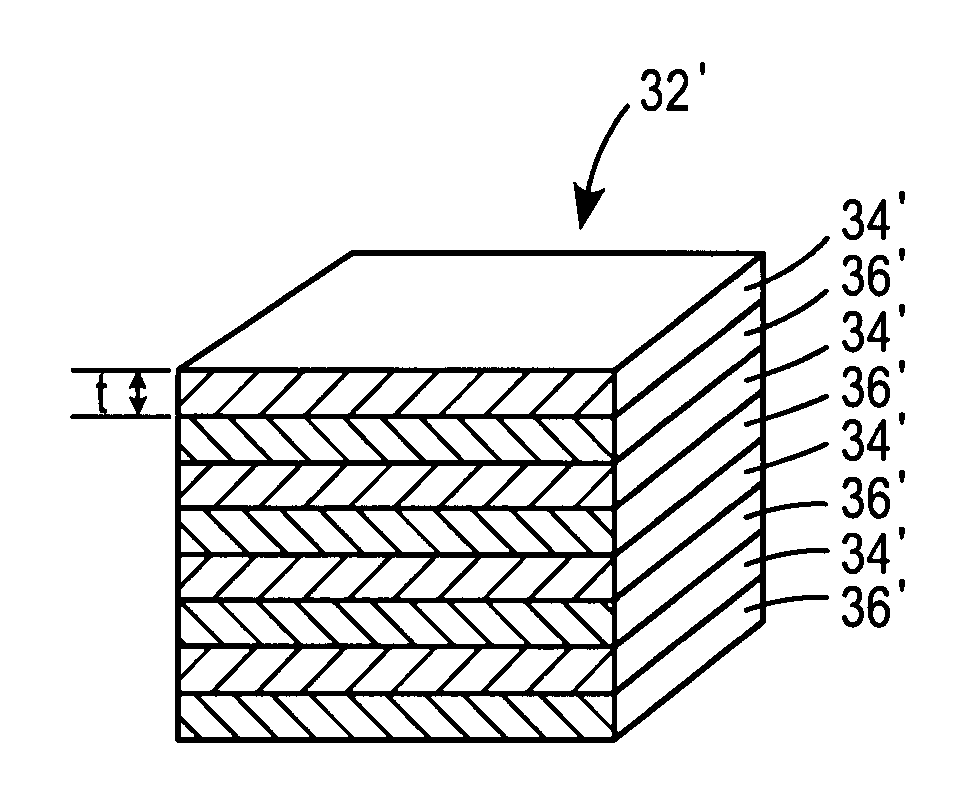
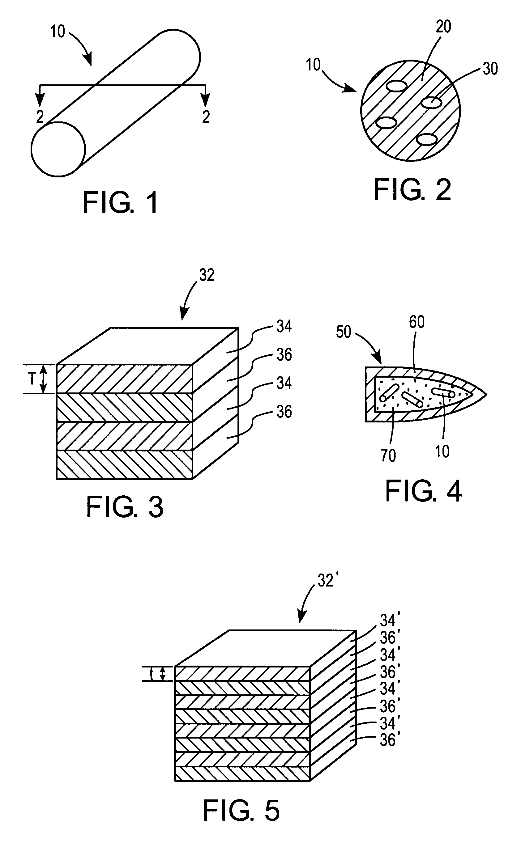
[0020]One embodiment of a reactive fragment 10 formed according to the principles of the present invention is illustrated in FIG. 1. According to the illustrated embodiment, the fragment 10 has a generally cylindrical geometry. However, it should be understood that any suitable geometry is comprehended by the scope of the present invention. Thus, the fragment 10 could also be formed with a spherical, polygonal, or other suitable geometry which renders it effective for its intended purpose.

[0021]As illustrated in FIG. 2, the reactive fragment 10 generally comprises a binder material 20 having a reactive energetic material 30 dispersed therein.

[0022]The binder material 20 can be formed from any suitable material. According to one embodiment, the binder material 20 comprises a polymeric material, including, but not limited to any epoxy or a polymer containing at least one azide group. According to a further optional embodiment, the binder may comprise a thermoplastic material such as p...


PUM

PropertyMeasurementUnit
thicknessaaaaaaaaaa
velocitiesaaaaaaaaaa
thicknessaaaaaaaaaa

Abstract

A munition is described including a reactive fragment having an energetic material having a least one layer of a reducing metal or metal hydride and at least one layer of a metal oxide dispersed in a binder material. A method is also described including forming a energetic material; including combining the energetic material having a least one layer of a reducing metal or metal hydride and at least one layer of a metal oxide with a polymeric binder material to form a mixture; and shaping the mixture to form a reactive fragment. The munition may be in the form of a warhead, and the reactive fragment may be contained within a casing of the warhead.

Description

FIELD OF THE DISCLOSURE[0001]The present disclosure relates to energetic compositions containing a reactive thin-film for reactive fragment munitions. More specifically, the present disclosure relates to reactive fragments based, at least in part, on reactive thin-film energetic materials dispersed in a matrix.BACKGROUND[0002]In the discussion that follows, reference is made to certain structures and / or methods. However, the following references should not be construed as an admission that these structures and / or methods constitute prior art. Applicant expressly reserves the right to demonstrate that such structures and / or methods do not qualify as prior art.[0003]A conventional munition includes a container housing, a high explosive, and optionally, fragments. Upon detonation of the high explosive, the container is torn apart forming fragments that are accelerated outwardly. In addition, to the extent that fragments are located within the container, these internal fragments are als...

Claims


Application Information

Patent Timeline
Patent Type & Authority Patents(United States)
IPC IPC(8): C06B45/00D03D43/00C06B33/00D03D23/00C06B45/12C06B45/16
CPCF42B12/202F42B12/44F42B12/22F42B12/204
Inventor HUGUS, GEORGE D.SHERIDAN, EDWARD W.
Owner LOCKHEED MARTIN CORP
Learn More