
Wavelength tuning source based on a rotatable reflector

a wavelength tuning source and reflector technology, applied in the field of optical wavelength filter systems, can solve the problems of limiting the maximum tuning speed, the sweep frequency previously demonstrated is less than 1 khz limited by the finite tuning speed of the filter, and achieves the effect of narrow instantaneous line width and broad spectral tuning rang

Inactive Publication Date: 2011-05-24
THE GENERAL HOSPITAL CORP
View PDF478 Cites 17 Cited by
  • Summary
  • Abstract
  • Description
  • Claims
  • Application Information

AI Technical Summary

Benefits of technology

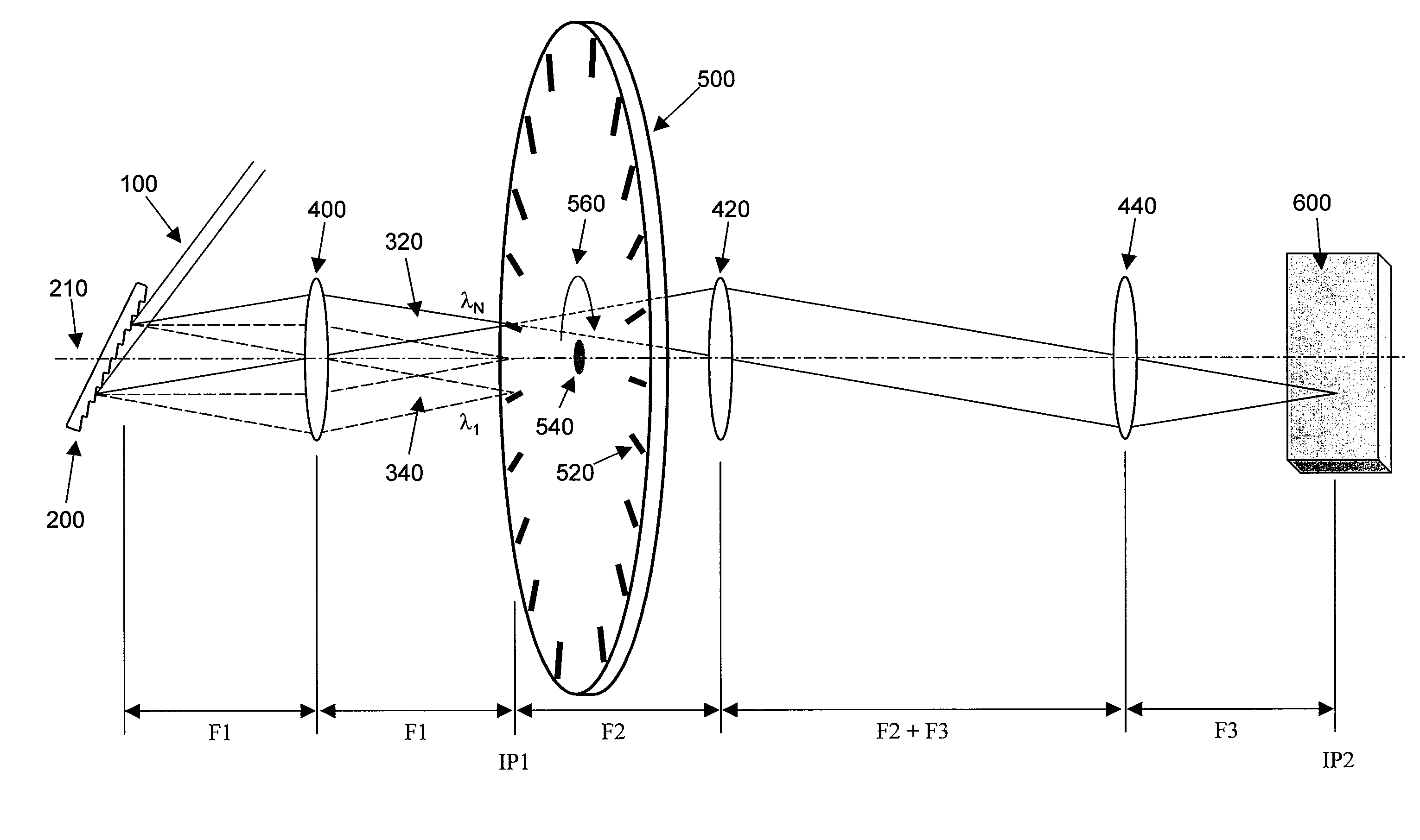
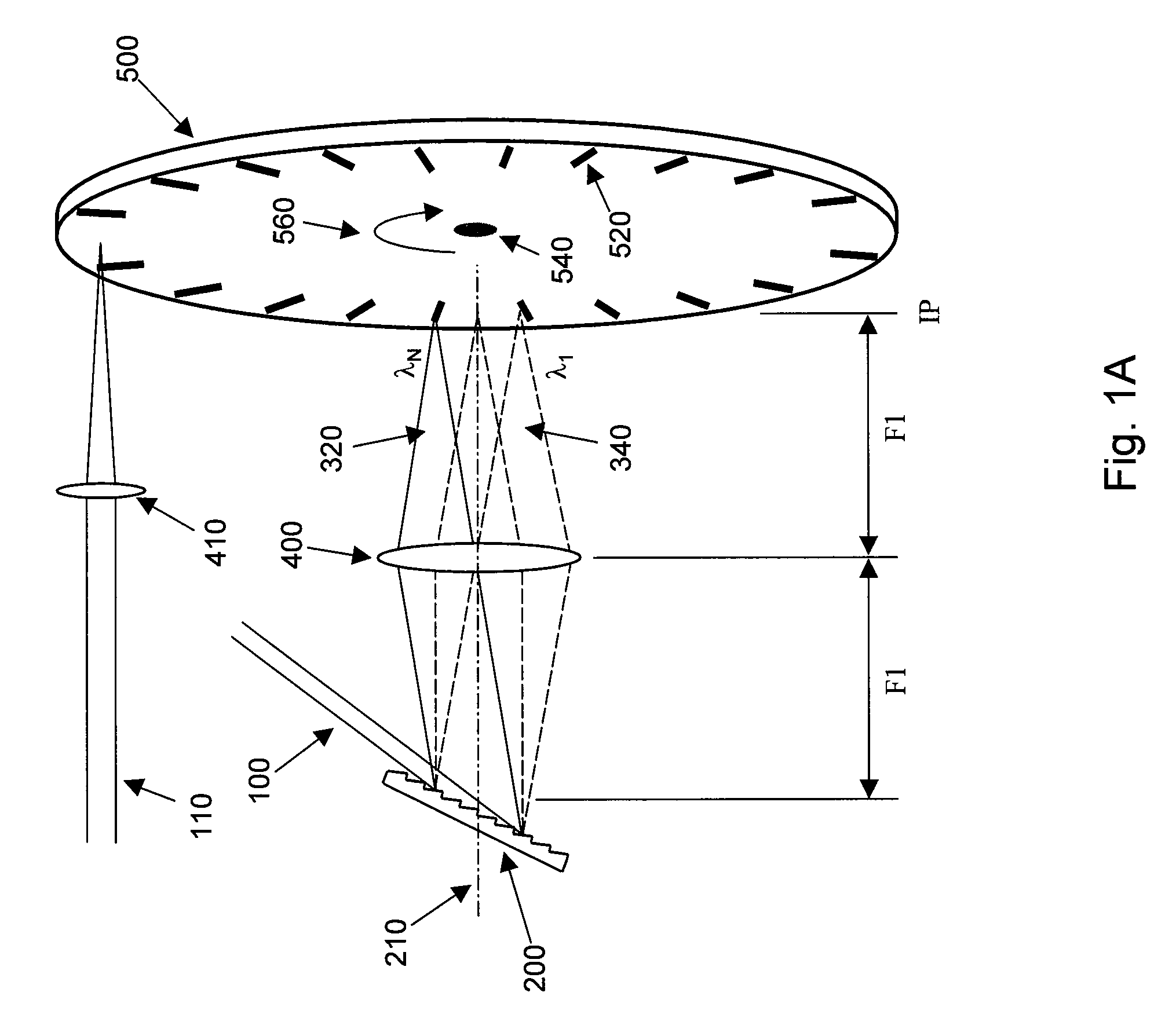
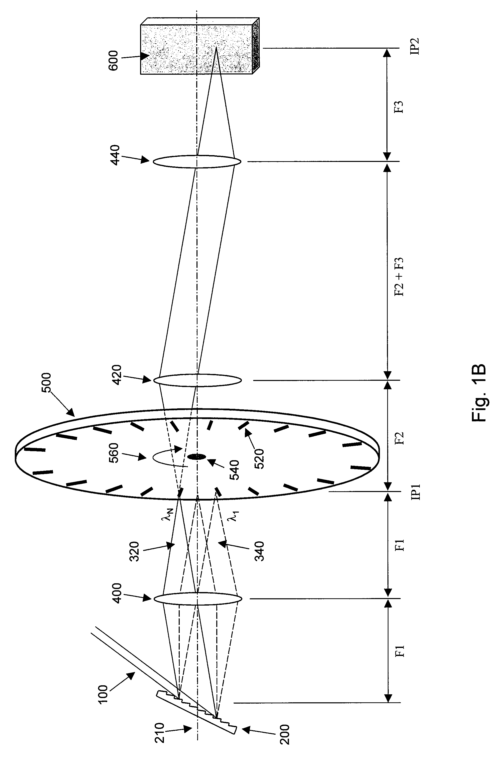
The present invention provides an apparatus and method for high-speed wavelength-swept light with broad spectral tuning range and narrow instantaneous linewidth. The apparatus includes a diffraction grating, focusing lens, and spinning disk, which can be combined with a proper gain medium to create a wavelength tunable light source. The filter and gain medium can be incorporated into a laser cavity. The invention also provides an electromagnetic radiation source that can emit a narrow band spectrum with its center wavelength being rapidly swept over a broad wavelength range. The arrangement includes a continuously rotating disk that reflects and / or transmits the second electromagnetic radiation to a particular location. The roundtrip travel time of the second electromagnetic radiation in the laser cavity can be controlled, and the relationship between the roundtrip travel time and the characteristic repetition time can be determined and controlled. The invention also provides an apparatus for amplifying at least one of the first and second electromagnetic radiation based on at least one Raman amplification characteristic.

Problems solved by technology

Obtaining single-frequency laser operation and ensuring mode-hop-free tuning, however, may use a complicated mechanical apparatus and can limit the maximum tuning speed.
However, the sweep frequency previously demonstrated has been less than 1 kHz limited by finite tuning speeds of the filters.

Method used


Image

  • Wavelength tuning source based on a rotatable reflector
  • Wavelength tuning source based on a rotatable reflector
  • Wavelength tuning source based on a rotatable reflector

Examples


Embodiment Construction

[0008]An exemplary embodiment of the present invention can be provided which may include apparatus and source arrangement for lightwave filtering that provides high-speed wavelength-swept light with broad spectral tuning range and narrow instantaneous linewidth. In exemplary variant of the exemplary embodiment of the present invention, the optical filter can include a diffraction grating, a focusing lens and a spinning disk. The spinning disk can have reflector patterns and / or transmission window patterns. Certain optical components and arrangement and a proper design of the disk enables high-speed wavelength sweeping over a broad tuning range with narrow instantaneous linewidth.

[0009]In another exemplary embodiment of present invention, the wavelength-swept filter is combined with a proper gain medium implementing a wavelength tunable light source. The filter and gain medium may further be incorporated into a laser cavity. For example, a laser can emit a narrow band spectrum with i...


PUM


Abstract

An apparatus and source arrangement for filtering an electromagnetic radiation can be provided which may include at least one spectral separating arrangement configured to physically separate one or more components of the electromagnetic radiation based on a frequency of the electromagnetic radiation. The apparatus and source arrangement may also have at least one continuously rotating optical arrangement, e.g., polygonal scanning mirror and spinning reflector disk scanner, which is configured to receive at least one signal that is associated with the one or more components. Further, the apparatus and source arrangement can include at least one beam selecting arrangement configured to receive the signal.

Description

CROSS-REFERENCE TO RELATED APPLICATION(S)[0001]This application is based upon and claims the benefit of priority from U.S. Patent Application Ser. No. 60 / 885,660, filed Jan. 19, 2007, the entire disclosure of which is incorporated herein by reference.FIELD OF THE INVENTION[0002]The present invention relates generally to optical systems, and more particularly to an optical wavelength filter system for wavelength tuning and a wavelength-swept laser using the optical wavelength filter system.BACKGROUND INFORMATION[0003]Considerable effort has been devoted for developing rapidly and widely tunable wavelength laser sources for optical reflectometry, biomedical imaging, sensor interrogation, and tests and measurements. A narrow line width, wide-range and rapid tuning have been obtained by the use of an intra-cavity narrow band wavelength scanning filter. Mode-hopping-free, single-frequency operation has been demonstrated in an extended-cavity semiconductor laser by using a diffraction gra...

Claims


Application Information

Patent Timeline
Patent Type & Authority Patents(United States)
IPC IPC(8): H01S5/14
CPCG01J3/02G01J3/021G01J3/0229G01J3/06G01J3/10G02B26/002H01S3/106H01S3/08063G02B26/04H01S3/08H01S3/08009H01S3/0805H01S3/10046H01S3/105
Inventor BOUMA, BRETT E.YUN, SEOK-YUNOH, WANG-YUHLVAKOC, BENJAMIN J.TEARNEY, GUILLERMO J.
Owner THE GENERAL HOSPITAL CORP
Learn More