
Self-similar laser oscillator

a laser oscillator and self-similar technology, applied in the field of lasers, can solve the problems of affecting the performance of the laser, the length of the gain segment is minimized, and the solution cannot meet periodic boundary conditions, so as to achieve the effect of effectively decoupling bandwidth filtering, broadening the bandwidth and reducing the length of the gain segmen

Inactive Publication Date: 2005-08-04
CORNELL RES FOUNDATION INC
View PDF9 Cites 83 Cited by
  • Summary
  • Abstract
  • Description
  • Claims
  • Application Information

AI Technical Summary

Benefits of technology

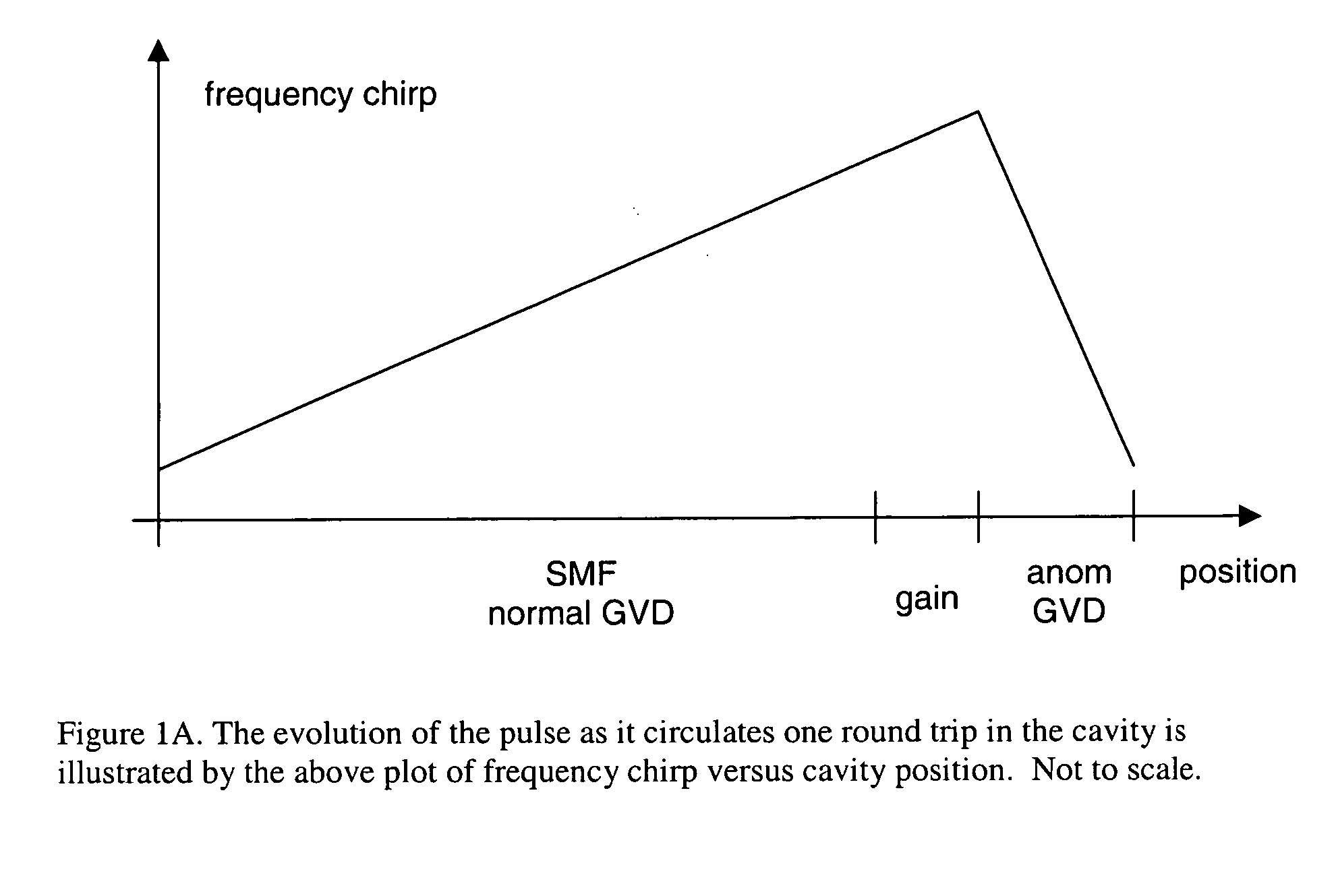
[0013] A model fiber laser cavity includes a segment of single-mode fiber (SMF) with normal dispersion that forms a large portion of the cavity length. The pulse propagating in the cavity has a central wavelength that lies within the gain profile of the gain medium. As the pulse propagates through the SMF fiber, its bandwidth is broadened through nonlinear interaction with the material. This effect operates in combination with group velocity dispersion (GVD) to create an approximately linear chirp on the pulse. Amplification is provided by a segment with gain sufficient to achieve the desired pulse energy. The length of this gain segment is minimized so that the pulse will experience negligible GVD and nonlinearity during amplification—effectively decoupling bandwidth filtering from nonlinear evolution in the fiber. The gain fiber is followed by an effective saturable absorber (SA), which may also serve as an output coupler. The final element is a dispersive delay line (DDL) that provides anomalous dispersion with negligible nonlinearity. Chirp accumulated in self-similar propagation will be compensated by the DDL, while any excess bandwidth will be filtered by the gain medium. This configuration produces a self-consistent solution in the resonator cavity and results in stable operation of the laser. The evolution of the pulse as it circulates one round trip in the cavity is illustrated by the plot of frequency chirp versus cavity position, shown in FIG. 1A.
[0022] In another preferred embodiment the gain in the laser cavity comprises a segment of rare-earth doped material, such as neodymium- or ytterbium- or erbium- or thulium-doped material and may also include more than one dopant (known as a co-dopant) for purposes such as facilitating energy transfer from a specific pump wavelength to the absorption wavelength of the gain material. The rare-earth doped material preferably possesses net positive group velocity dispersion.

Problems solved by technology

The energy of the pulses generated in fiber laser oscillators is generally limited by effects that cause the pulse to break up into several pulses (called wave-breaking.)
Wave-breaking is a consequence of excessive nonlinearity within the oscillator cavity—a limitation that is particularly problematic in ultrashort pulse fiber lasers where the small beam diameter produces high intensities and therefore large nonlinear phase shifts.
This is novel, and has not been anticipated in prior art laser oscillators.
Such a solution cannot satisfy periodic boundary conditions.
However, self-similar propagation of intense pulses is disrupted if the pulse encounters a limitation to its spectral bandwidth.

Method used


Image

  • Self-similar laser oscillator
  • Self-similar laser oscillator
  • Self-similar laser oscillator

Examples


Embodiment Construction

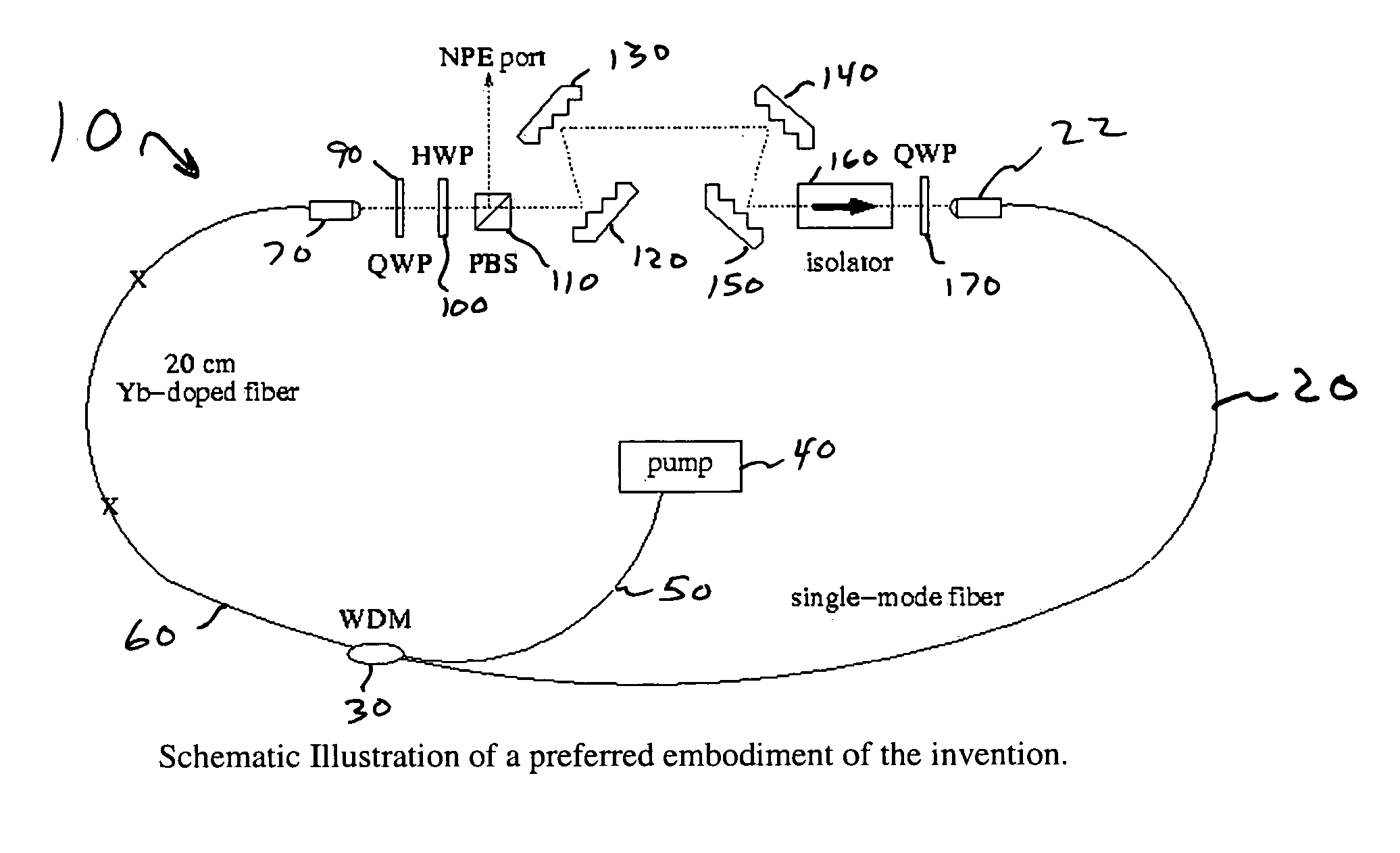
[0053] Referring now to FIG. 2, the fiber laser 10 of the invention is shown as a ring laser. The fiber laser of the invention could also be configured as a figure-eight cavity, linear cavity or other suitable laser geometry, as will be understood by those skilled in the art. The ring geometry described herein is but one example of the many geometries to which the invention could be applied.

[0054] The fiber ring laser of FIG. 2 comprises several segments. On the right side of the ring, we see segment 20 of the ring laser 10 of the invention comprises the majority of the optical length of the cavity and generally supports only a single spatial mode. In a preferred embodiment this segment of fiber single mode fiber (SMF) has a length of 4 meters. Segment 20 is characterized by a net positive group velocity dispersion (also referred to as net normal dispersion). One end of segment 20 is connected a collimator 22 to receive a pulse circulating in the cavity. The other end is connected ...


PUM


Abstract

A laser producing high energy ultrashort laser pulses comprises a normal dispersion segment, a gain segment, an anomalous dispersion segment with negligible nonlinearity and an effective saturable absorber arranged to form a laser cavity. Each segment is optically interconnected so that a laser pulse will propagate self-similarly therein. (A pulse that propagates in a self-similar manner is sometimes referred to as a “similariton.”) With this laser the limitations of prior art laser oscillators are avoided. Also provided are means for pumping the gain medium in the laser cavity, and means for extracting laser pulses from the laser cavity. The laser cavity is preferably a ring cavity. Preferably the laser is configured to achieve unidirectional circulation of laser pulses therein. This configuration is scalable to much higher pulse energy than lasers based on soliton-like pulse shaping.

Description

STATEMENT REGARDING FEDERALLY SPONSORED RESEARCH OR DEVELOPMENT [0001] This invention was made with government support under contract (enter contract numbers). The government has certain rights in this invention.CROSS-REFERENCE TO RELATED APPLICATIONS [0002] None. REFERENCE TO A “SEQUENCE LISTING”[0003] Not applicable. BACKGROUND OF THE INVENTION [0004] 1. Field of the Invention [0005] This invention relates to lasers, and more particularly to fiber lasers. [0006] 2. Description of Related Art [0007] Lasers, particularly those partially or wholly incorporating optical fibers, have emerged as attractive sources of extremely short pulses of light. Fibers lasers are of particular interest because they can be tightly coiled to produce long path lengths in compact geometries. And because fiber lasers can be hard-wired, they can be made impervious to adverse environmental effects—especially when the polarization is fixed in a manner that makes them relatively insensitive to mechanically a...

Claims


Application Information

Patent Timeline
Patent Type & Authority Applications(United States)
IPC IPC(8): H01S3/00H01S3/067H01S3/083H01S3/098H01S3/16
CPCH01S3/06708H01S3/06725H01S2301/085H01S3/1115H01S3/1618H01S3/06791
Inventor ILDAY, FATIH OMERWISE, FRANKCLARK, WILLIAM G.
Owner CORNELL RES FOUNDATION INC
Learn More