
Treatment chamber for separating compounds from aqueous effluent

a technology for separating compounds and aqueous effluent, which is applied in the direction of electrochemical treatment of water/sewage, disinfection, energy-based chemical/physical/physico-chemical processes, etc. it can solve the problems of increasing the time and cost of the removal of unbound dyes, requiring large volumes of adsorbent to perform effectively, and reducing the efficiency of the removal process. , to achieve the effect of reducing the hydrodynamic boundary layer, reducing the tim

Inactive Publication Date: 2011-05-24
KIMBERLY-CLARK WORLDWIDE INC
View PDF306 Cites 4 Cited by
  • Summary
  • Abstract
  • Description
  • Claims
  • Application Information

AI Technical Summary

Benefits of technology

"The present patent is about a process for removing compounds from aqueous effluents using a treatment chamber with an ultrasonic waveguide assembly. The process involves introducing the effluent through an inlet port of the chamber, ultrasonically energizing and electrically charging the outer surface of the waveguide assembly, and exhausting the cleaned effluent from an outlet port of the chamber. The technical effect of this process is faster and more efficient removal of compounds from aqueous effluents compared to conventional plug flow reactors. The patent also describes different variations of the process for removing different types of compounds from different types of effluents."

Problems solved by technology

During these reactions, such materials or resins adsorb the dyes and other soluble components in the textile effluent slowly and require large volumes of the adsorbent to perform effectively.
One problem with processing textile effluent through a column such as that of a conventional plug flow reactor, is that many of the compounds to be adsorbed (e.g., dyes and reactants) must travel through a hydrodynamic boundary layer surrounding the bead or particle.
This boundary layer is a source of resistance for the compounds, which prolongs the adsorption process and increases time and costs of the removal of unbound dyes and reactants from textile effluents.
Additionally, there is increased pressure drop across the reactor, and as such, larger plug flow reactor geometries and processing equipment are required.

Method used


Image

  • Treatment chamber for separating compounds from aqueous effluent
  • Treatment chamber for separating compounds from aqueous effluent
  • Treatment chamber for separating compounds from aqueous effluent

Examples


Embodiment Construction

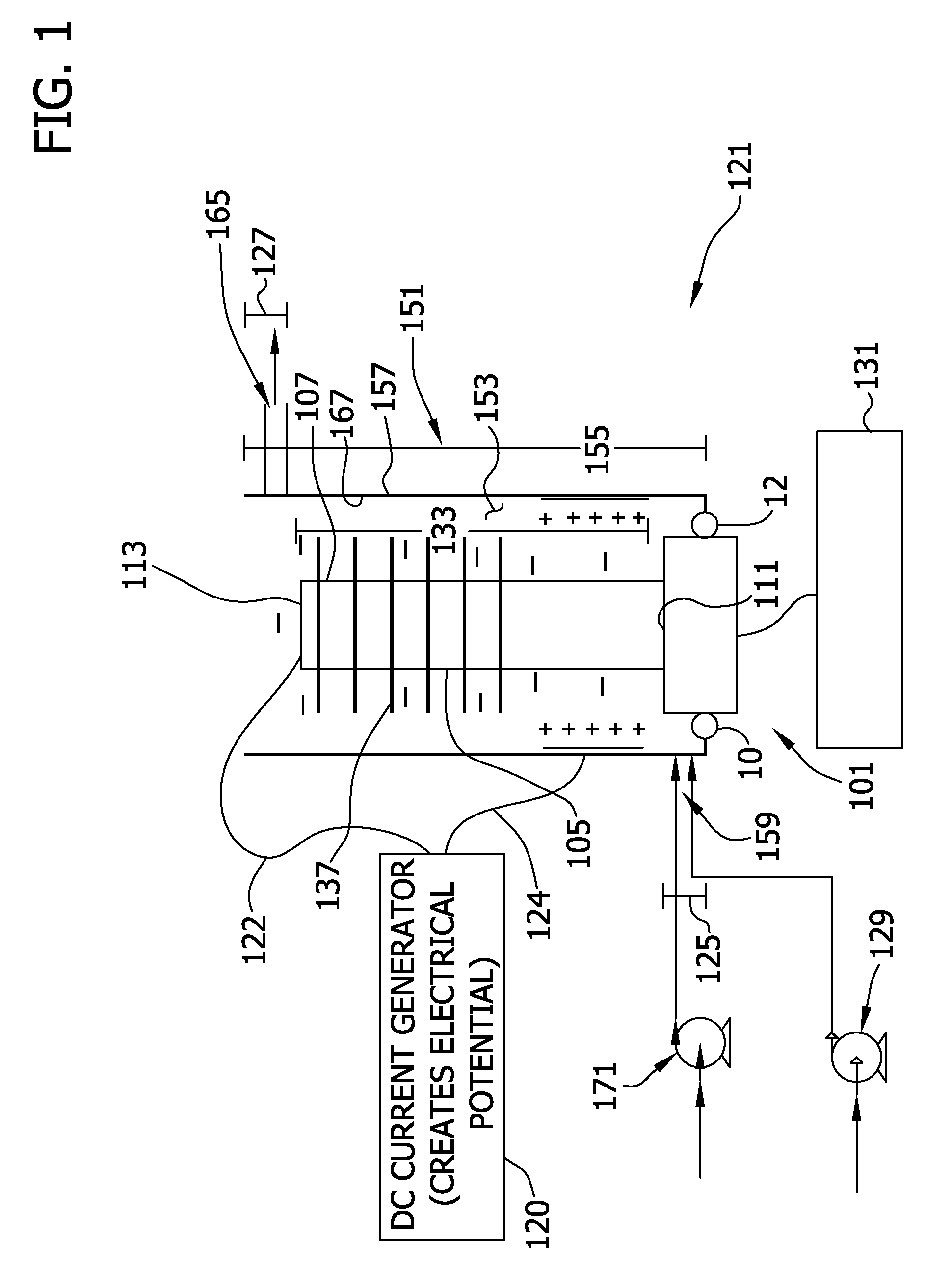
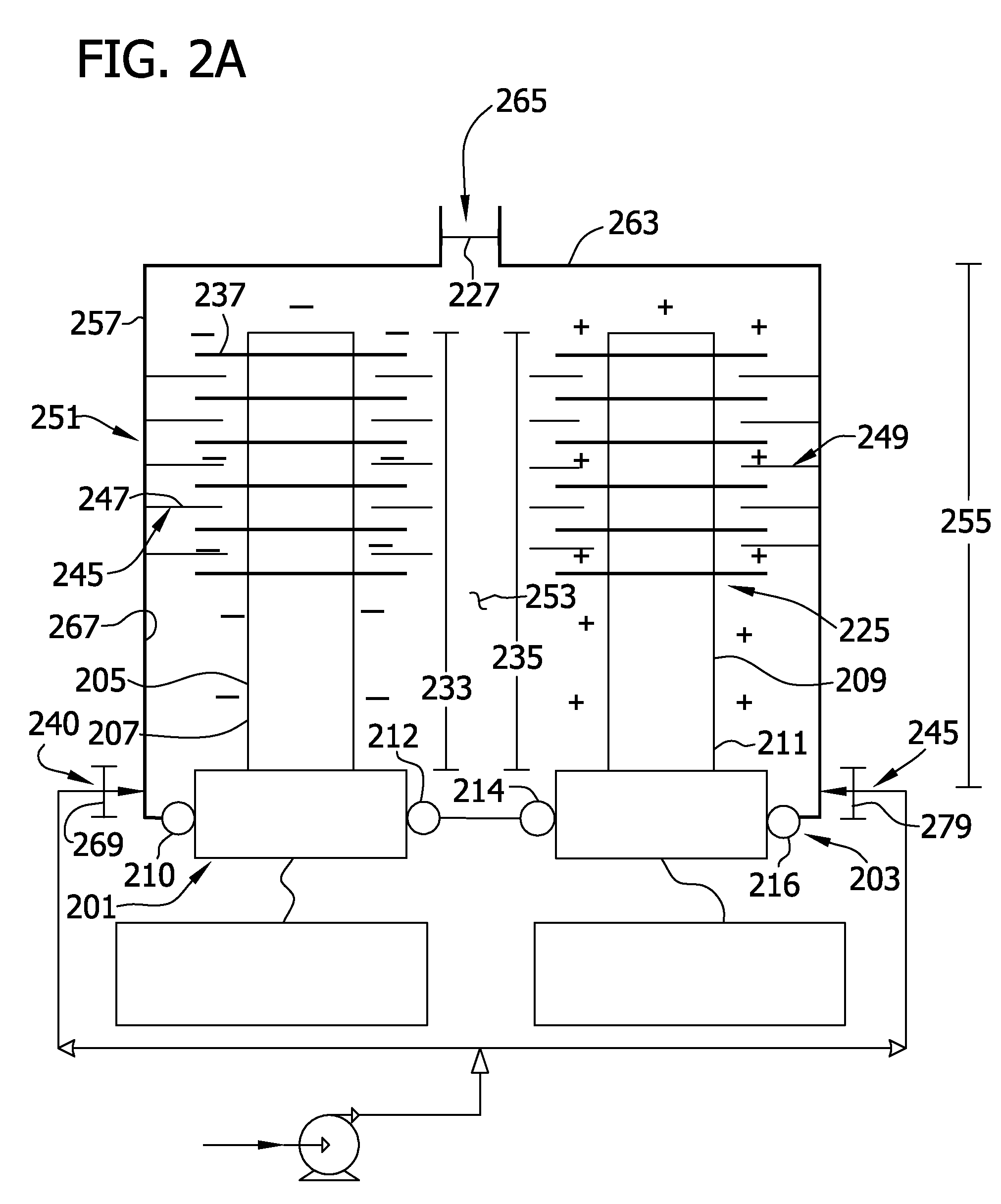
[0024]The present disclosure is generally directed to a treatment chamber for removing compounds from aqueous effluent. Specifically, in one embodiment, the treatment chamber is capable of removing compounds such as nitrogen, chlorine, and oxygen from waste water, such as through the process of electrolysis. For example, the treatment chamber is used in processes using both ultrasonics and electrolysis to degrade compounds such as water and ammonia into less complex components (e.g., oxygen, nitrogen, hydrogen, and the like). Additionally, the processes can be used in the reduction of metal ions to precipitate the metals out of solution (e.g., gold, copper, silver, and the like. In another embodiment, the treatment chamber removes dyes and reactants from textile effluent. In yet another embodiment, the treatment chamber removes microorganisms and other contaminants from drinking water.

[0025]FIG. 1 provides a treatment chamber, generally indicated at 121, for removing compounds from ...


PUM

PropertyMeasurementUnit
pressureaaaaaaaaaa
pressureaaaaaaaaaa
frequencyaaaaaaaaaa

Abstract

Processes of using treatment chambers for separating compounds in an aqueous effluent are disclosed. More particularly, the treatment chambers use ultrasonic energy and an electrode potential to provide efficient and effective removal of compounds from aqueous effluents, such as textile effluents.

Description

BACKGROUND OF DISCLOSURE[0001]The present disclosure generally relates to treatment chambers for separating compounds in an aqueous solution. More particularly, the present disclosure relates to treatment chambers that use ultrasonic energy and an electrode potential to provide efficient and effective removal of compounds from aqueous effluents, such as textile effluents.[0002]In nearly all textile dyeing and printing processes, some fraction of the applied colorant will not bind to the substrate. These unbound dyes and reactants are typically removed by a water rinsing process, generating large quantities of textile effluent that must be disposed in an environmentally acceptable manner.[0003]Previous attempts have disposed of the textile effluent by passing the effluent through an ion exchange resin or activated carbon. During these reactions, such materials or resins adsorb the dyes and other soluble components in the textile effluent slowly and require large volumes of the adsorb...

Claims


Application Information

Patent Timeline
Patent Type & Authority Patents(United States)
IPC IPC(8): C02F1/46C02F1/36
CPCC02F1/36C02F1/4672C02F2103/30C02F2101/308C02F1/722
Inventor JANSSEN, ROBERT ALLENAHLES, JOHN GLENEHLERT, THOMAS DAVIDMACDONALD, JOHN GAVINMCCRAW, JR., EARL C.MCNICHOLS, PATRICK SEANRASMUSSEN, PAUL WARRENROFFERS, STEVE
Owner KIMBERLY-CLARK WORLDWIDE INC
Learn More