
Liquid-crystal display device and method of driving liquid-crystal display device

a display device and liquid crystal technology, applied in the field of display devices, can solve the problems of deterioration of image quality of adverse influence caused by leak current cannot be neglected, voltage drop caused by large leak current, etc., and achieve the effect of reducing power consumption of active matrix type liquid crystal display devices, reducing flickering phenomena, and reducing power consumption

Active Publication Date: 2006-01-12
PANASONIC LIQUID CRYSTAL DISPLAY CO LTD +1
View PDF4 Cites 36 Cited by
  • Summary
  • Abstract
  • Description
  • Claims
  • Application Information

AI Technical Summary

Benefits of technology

The present invention provides a liquid crystal display device that can be driven in low power consumption while suppressing flickering in a partial display mode. The invention features a driving method that involves scanning the partial display area in a certain period and maintaining a constant potential for the common electrode during the scanning period. This results in reduced flickering and improved picture quality. The invention also includes a liquid crystal display device that can be driven in the partial display mode while reducing power consumption. Overall, the invention provides a solution for improving the performance of liquid crystal display devices in low power consumption while maintaining high quality.

Problems solved by technology

In such a case that a leak current is large, a voltage drop caused by this large leak current may occur.
In particular, when a time period for holding the voltage Valc is sufficiently longer than 1 / 60 seconds, the adverse influence caused by the leak current cannot be neglected.
Since the flickering having such lower frequencies may be easily sensed, image qualities of liquid crystal display devices may be considerably deteriorated.

Method used


Image

  • Liquid-crystal display device and method of driving liquid-crystal display device
  • Liquid-crystal display device and method of driving liquid-crystal display device
  • Liquid-crystal display device and method of driving liquid-crystal display device

Examples


embodiment 1

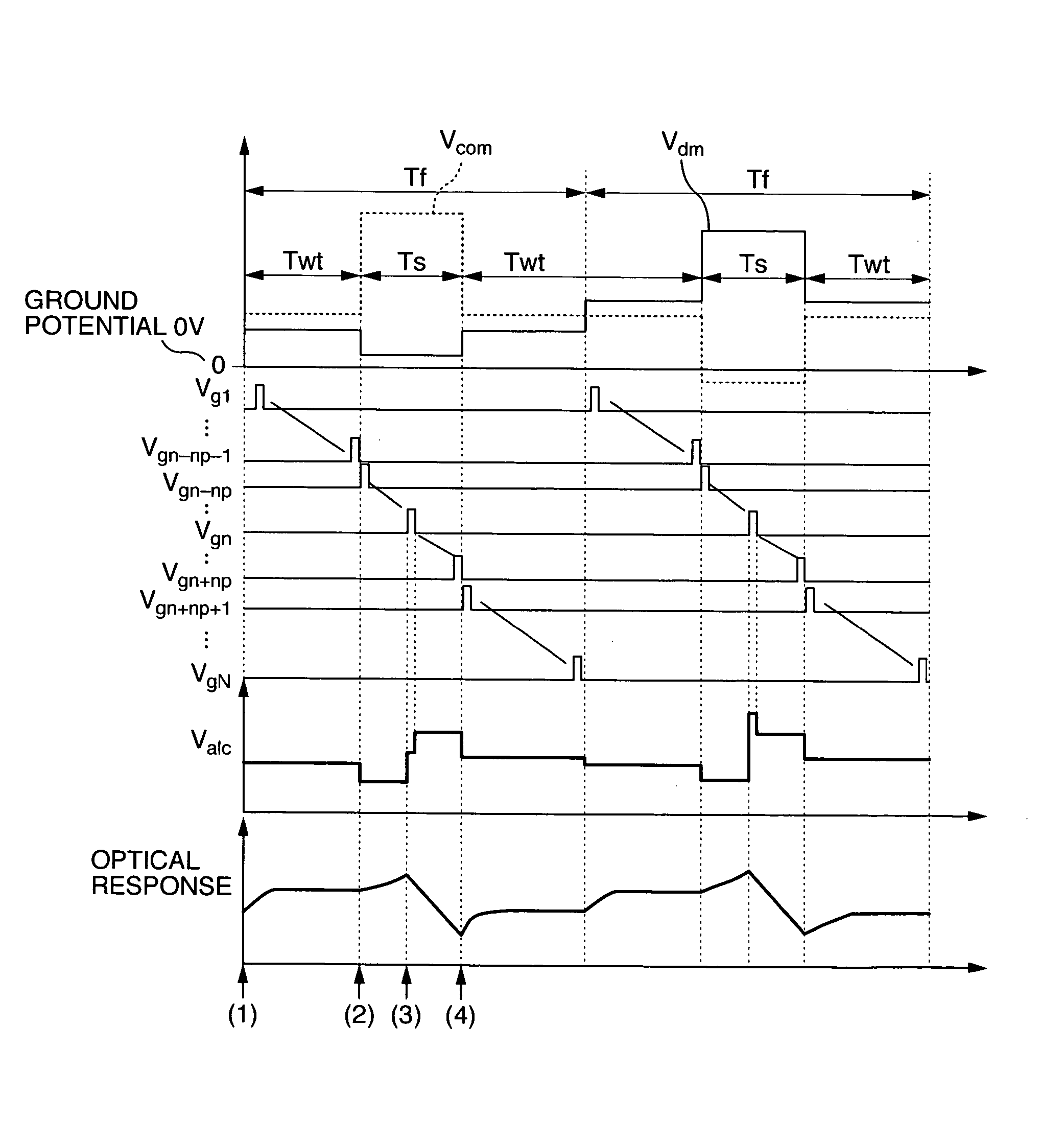
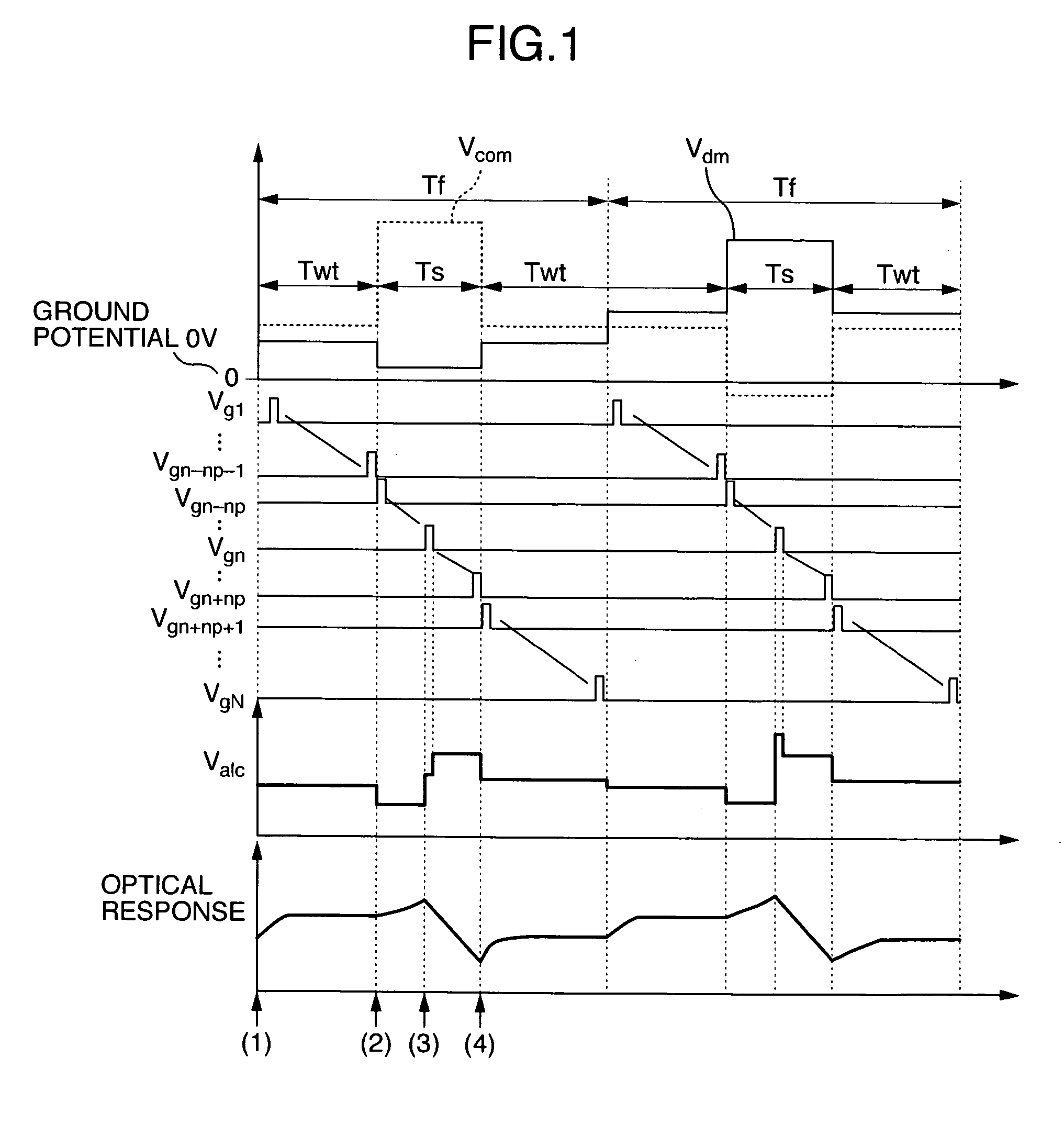
[0054] Now, with reference to FIG. 1, a description is made of summarized operations in the case that a partial display operation is carried out by way of a driving method according to an embodiment 1 of the present invention in pixels defined from an (n−np)-th row up to an (n+np)-th row, which contain a pixel of an n-th row. FIG. 1 represents a timing chart of a driving method for driving two continued frames; a voltage “Valc” of a pixel defined by the n-th row and an m-th column; and an optical response of the pixel. This timing chart of the driving method corresponds to such a case that a background display area is displayed in white and a partial display area is displayed in black.

[0055] In the two frame periods, such a period other than a partially scanning period Ts will be referred to as a “blank period Twt.” In both the partially scanning period Ts and the blank period Twt, counter electrode potentials Vcom become constant potentials different from each other, and one parti...

embodiment 2

[0075] As indicated in FIG. 3, a driving method of an embodiment 2 of the present invention is featured by that in the driving method explained in the embodiment 1, a potential at a data line in a blank period Twt is kept constant. This driving method of the embodiment 2 will now be explained. Operations executed in such a case that a partial display operation is carried out in pixels defined from an (n−np)-th row up to an (n+np)-th row, which contain a pixel of an n-th row, will now be summarized.

[0076]FIG. 3 shows a timing chart of a driving method for driving two continued frames; a voltage “Valc” of a pixel defined by the n-th row and an m-th column; and an optical response of the pixel. This timing chart of the driving method corresponds to such a case that a background display area is displayed in white and a partial display area is displayed in black. In both a partially scanning period Ts and a blank period Twt, counter electrode potentials Vcom become constant potentials d...

embodiment 3

[0109] The above-explained embodiments 1 and 2 relate to the driving methods for suppressing the deteriorations of the picture qualities and for reducing the power consumption. This embodiment 3 of the present invention is directed to a reduction of electric power as to a driving apparatus of a liquid crystal display device.

[0110] In this embodiment 3, while a partial display mode and a normal display mode can be switched, an active matrix type liquid crystal display device is provided with the below-mentioned driving apparatus, and the liquid crystal display device performs a desirable display operation on a partial display area constituted by an arbitrarily-selected number of gate lines, and displays the background on the remaining background display area when the partial display mode is selected. In the driving apparatus, the respective gate lines of the partial display area are scanned in a certain period, and this period is set as a frame period; in such a case that “k” pieces...


PUM


Abstract

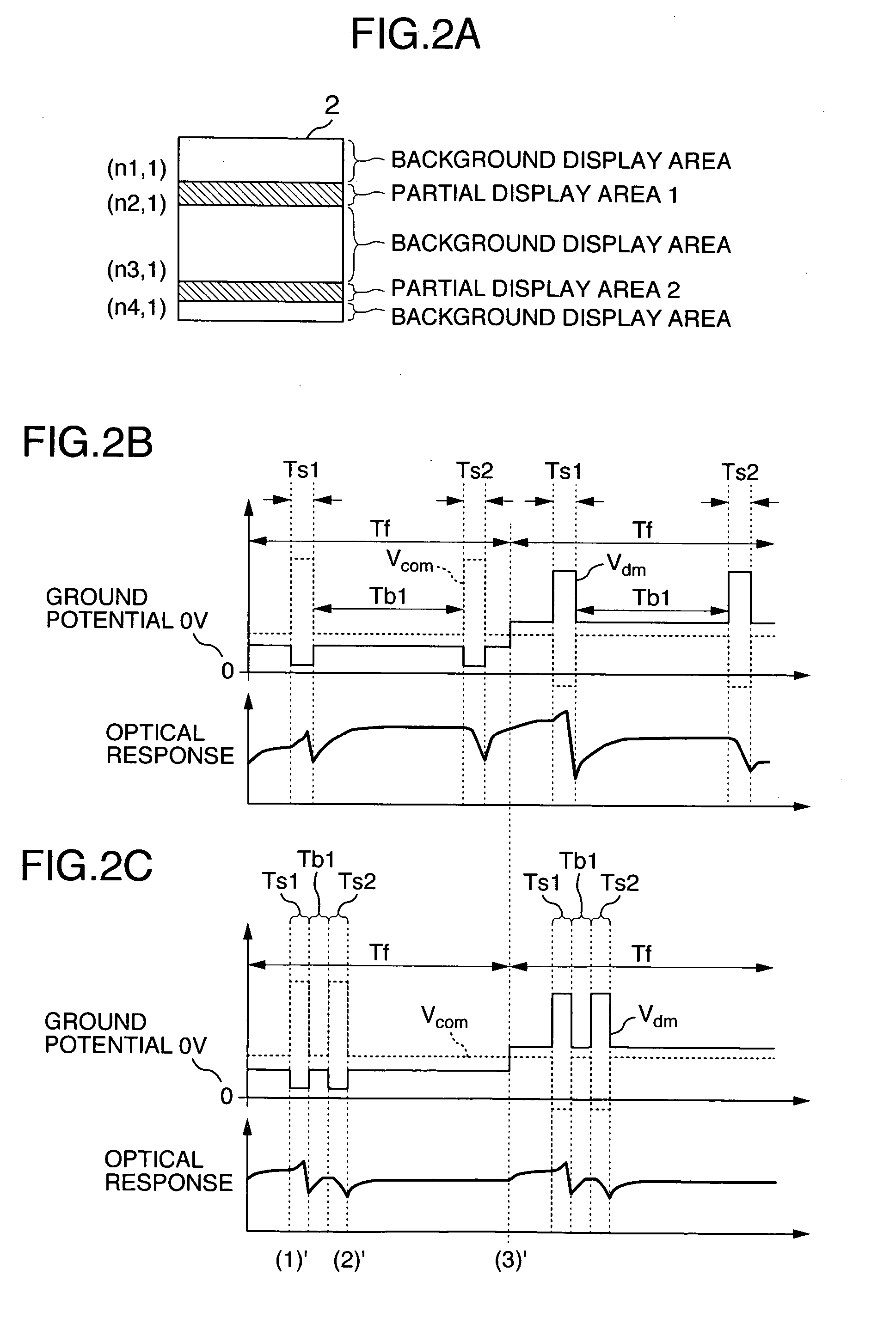
An active matrix type liquid crystal display device driving method for switching a partial display mode and a normal display mode. The respective data lines of the partial display area are scanned in a certain period defined as a frame period, “k” pieces (symbol “k” is integer larger than, or equal to 1) of the partial display areas are present within 1 screen, a common electrode potential is varied 2 k times within 1 frame period; a common electrode potential in a partially scanning period for scanning the partial display area is made as a constant potential against a reference of a driving circuit for driving the data lines; and within at least two continued frames, a common electrode potential of a blank period other than the partially scanning period is made as a constant potential which is different from the constant potential in the partially scanning period.

Description

CROSS-REFERENCE TO RELATED APPLICATION [0001] The present invention is related to (1) U.S. patent application Ser. No. 10 / 729,391 entitled “Liquid-Crystal Display Device and Method of Driving Liquid-Crystal Display Device” filed on Dec. 5, 2003. The disclosures of the above U.S. application is herein incorporated by reference.BACKGROUND OF THE INVENTION [0002] The present invention generally relates to a display apparatus of a mobile appliance such as cellular telephones. More specifically, the present invention is directed to a liquid crystal display device capable of realizing a high picture quality and operable in low power consumption. [0003] As a driving method for making a display on a so-called “partial display area” of a display panel and also for making a partial display on other display areas of this display panel, in which the background is displayed, the below-mentioned driving method has been disclosed in, for example, JP-A-2001-356746. That is, while a display device i...

Claims


Application Information

Patent Timeline
Patent Type & Authority Applications(United States)
IPC IPC(8): G09G3/36
CPCG09G3/3614G09G3/3655G09G2330/04G09G2330/021G09G2320/0247
Inventor SEKIGUCHI, YOSHIFUMIHIROTA, SHOICHIKOMURA, SHINICHI
Owner PANASONIC LIQUID CRYSTAL DISPLAY CO LTD
Learn More