
Method and system for extracting ion beams composed of molecular ions (cluster ion beam extraction system)

a molecular ion and beam extraction technology, applied in the field of ion optical systems, can solve the problems of insufficient traditional extraction optics for this application, poor match between thin plate optics, and increased beam losses, so as to reduce the effect of punching, increase beam losses, and reduce beam divergen

Inactive Publication Date: 2011-04-19
SEMEQUIP
View PDF6 Cites 8 Cited by
  • Summary
  • Abstract
  • Description
  • Claims
  • Application Information

AI Technical Summary

Benefits of technology

"The patent text describes a new type of triode extraction system that is designed for cluster ion beam extraction applications. This system is better suited for high current density extraction compared to traditional systems, as it minimizes beam cross over and shields the source from excess extraction electric fields. The new system also allows for smaller values of the extraction gap and a novel focusing feature that allows the beam to be either focused or de-focused in the non-dispersive plane by using a bipolar bias voltage of only a few kV over a broad range of beam energy. This solution is superior to a stand-alone electrostatic lens solution, which would require tens of kV of bias voltage in order to be able to focus an enertic beam. Overall, this new system improves the efficiency and accuracy of cluster ion beam extraction for various applications."

Problems solved by technology

The development of cluster ion beams (for example, B18Hx+, B10Hx+, C7Hx+) for next generation implanter technology, however, has exposed the inadequacy of traditional extraction optics for this application.
For low current density beam extraction, the thin plate optics setup is poorly matched, especially at higher energies.
The strong cross over also leads to high beam divergence which increases beam losses in mass analyzer magnet and in the following beam line due to beam vignetting, i.e., beam intersection with beam line apertures.

Method used


Image

  • Method and system for extracting ion beams composed of molecular ions (cluster ion beam extraction system)
  • Method and system for extracting ion beams composed of molecular ions (cluster ion beam extraction system)
  • Method and system for extracting ion beams composed of molecular ions (cluster ion beam extraction system)

Examples


Embodiment Construction

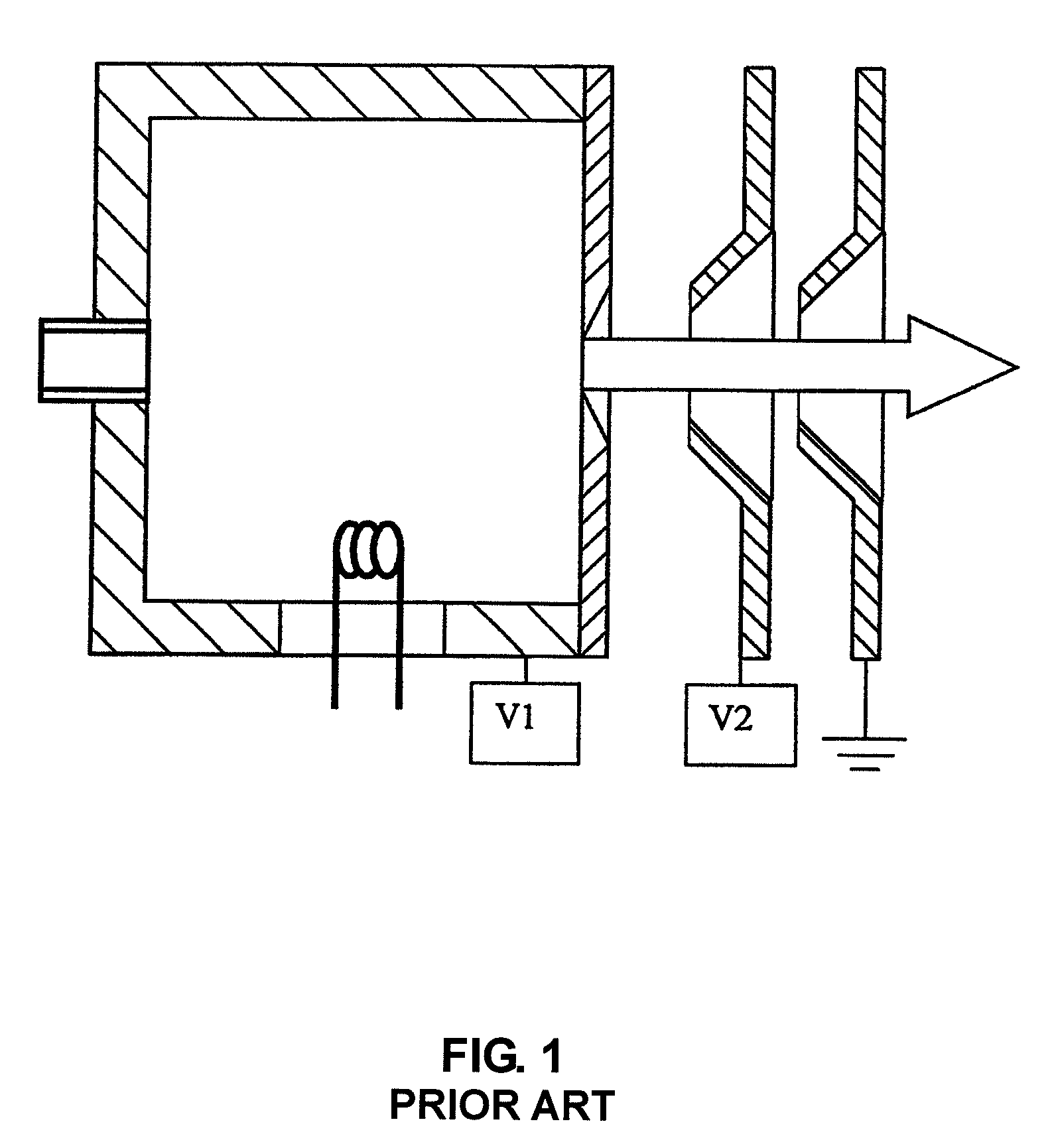
[0038]FIG. 1 shows a schematic of a traditional plasma ion source used in implanters. An ion source consists of a vacuum chamber, material feed port, ion extraction slot and ionization mechanism. The size of the chamber varies depending on the size of the ion beam that is created. Source material is fed into the source chamber either in vapor or gaseous form. The neutral feedstock is ionized using one of the following methods: arc discharge in several variations, RF- or microwave excitation or electron impact ionization. The created ions are extracted from the source through an opening in one of the source chamber walls.

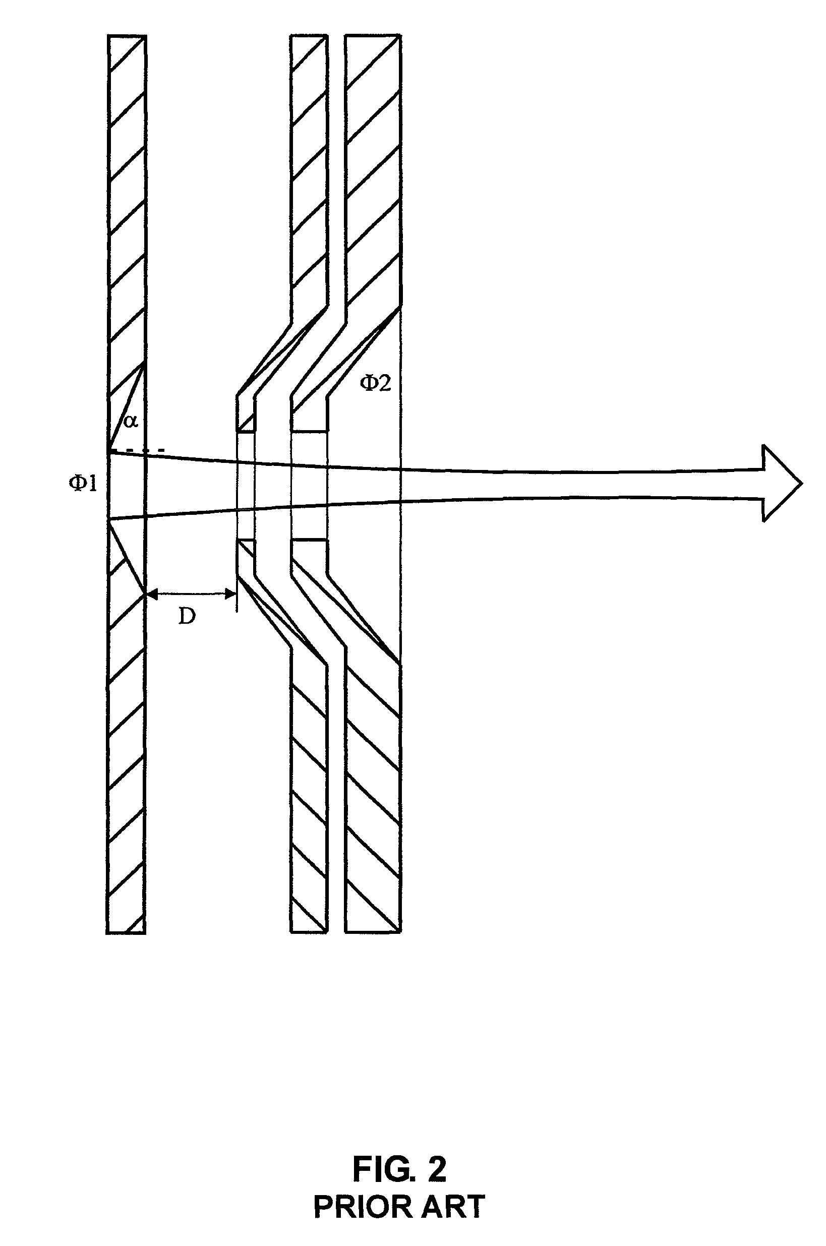
[0039]FIG. 2 shows a cross section of a typical ion implanter extraction system in dispersive plane. The horizontal or dispersive plane cross section shown is a representation of typical ion extraction system that is widely used in ion beam implantation. The extraction aperture size and shape can vary from application to application. High current density plasma sourc...


PUM


Abstract

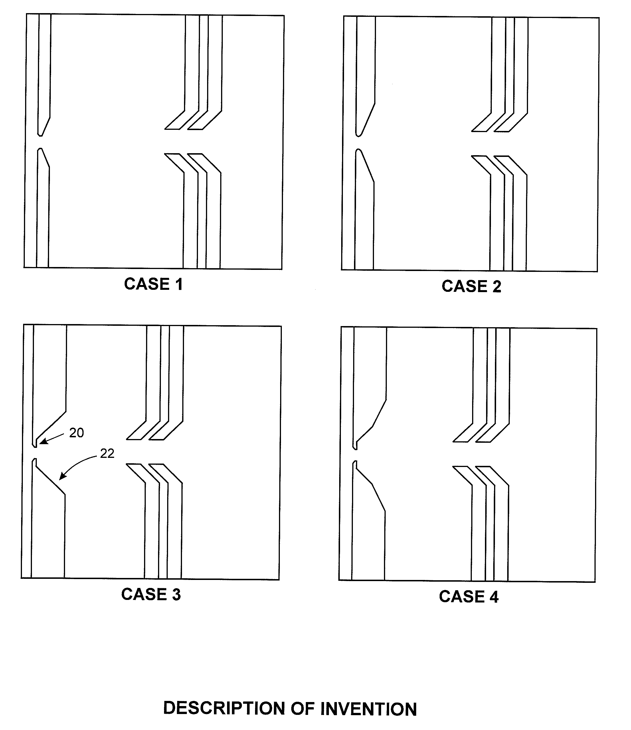
A new type of triode extraction system, a Cluster Ion Beam Extraction System, is disclosed for broad energy range cluster ion beam extraction applications while still being applicable to atomic and molecular ion species as well. The extraction aperture plate contours are set to minimize the beam cross over and at the same time shield the source from excess extraction electric fields thus allowing smaller values of the extraction gap. In addition, a novel focusing feature is integrated into these new optics which allows the beam to be either focused or de-focused in the non-dispersive plane by using a bipolar bias voltage of only a few kV over a broad range of beam energy. This is a superior solution to a stand-alone electrostatic lens solution, for example an einzel lens, which would require tens of kV of bias voltage in order to be able to focus an energetic beam.

Description

CROSS REFERENCE TO RELATED APPLICATIONS[0001]This application claims the priority to and the benefit of U.S. Provisional Patent Application No. 60 / 939,505, filed on May 22, 2007, hereby incorporated by reference.BACKGROUND OF THE INVENTION[0002]1. Field of the Invention[0003]The invention relates to an ion optical system that extracts and forms an ion beam which can be used for ion implantation processes, particularly in the low energy range 100 eV-4 keV. The invention enables a broad energy range of the transported ion beam and also enables the extraction of molecular ions as well as more conventional monomer ion beams using a simple triode extraction structure. Novel features are incorporated into the invention that enable beam formation and variable focusing of ion beams over a very broad range of beam current, ion mass and source brightness, while being compatible with many commercial beam line implantation platforms.[0004]2. Description of the Prior Art—Ion Implantation Process...

Claims


Application Information

Patent Timeline
Patent Type & Authority Patents(United States)
IPC IPC(8): H01J37/15
CPCH01J49/06
Inventor HORSKY, THOMAS N.HAHTO, SAMI K.
Owner SEMEQUIP
Learn More