
Display device, method of driving the display device, and electronic device

Active Publication Date: 2011-06-09
JOLED INC
View PDF4 Cites 8 Cited by
  • Summary
  • Abstract
  • Description
  • Claims
  • Application Information

AI Technical Summary

Benefits of technology

[0007]It is desirable to provide a display device that may be controlled to be reduced in power consumption, a method of driving the display device, and an electronic device having the display device.
[0014]According to the display device, the method of driving the display device, and the electronic device of the embodiment of the invention, a value of a power-supply voltage may be set small compared with a case where power-supply voltage is beforehand provided with a margin corresponding to predicted voltage variation in a light emitting element. Thus, power consumption may be controlled to be low.

Problems solved by technology

For example, when inter-terminal voltage of the organic EL element is expected to increase by about 2 V due to variation in the I-V characteristic of the element, power-supply voltage is likely to be beforehand set to a value having a margin of about 2 V. However, when power-supply voltage is beforehand provided with a margin, power consumption has disadvantageously increased in correspondence to such a margin.

Method used


Image

  • Display device, method of driving the display device, and electronic device
  • Display device, method of driving the display device, and electronic device
  • Display device, method of driving the display device, and electronic device

Examples


embodiment

Schematic Configuration of Display Device 1

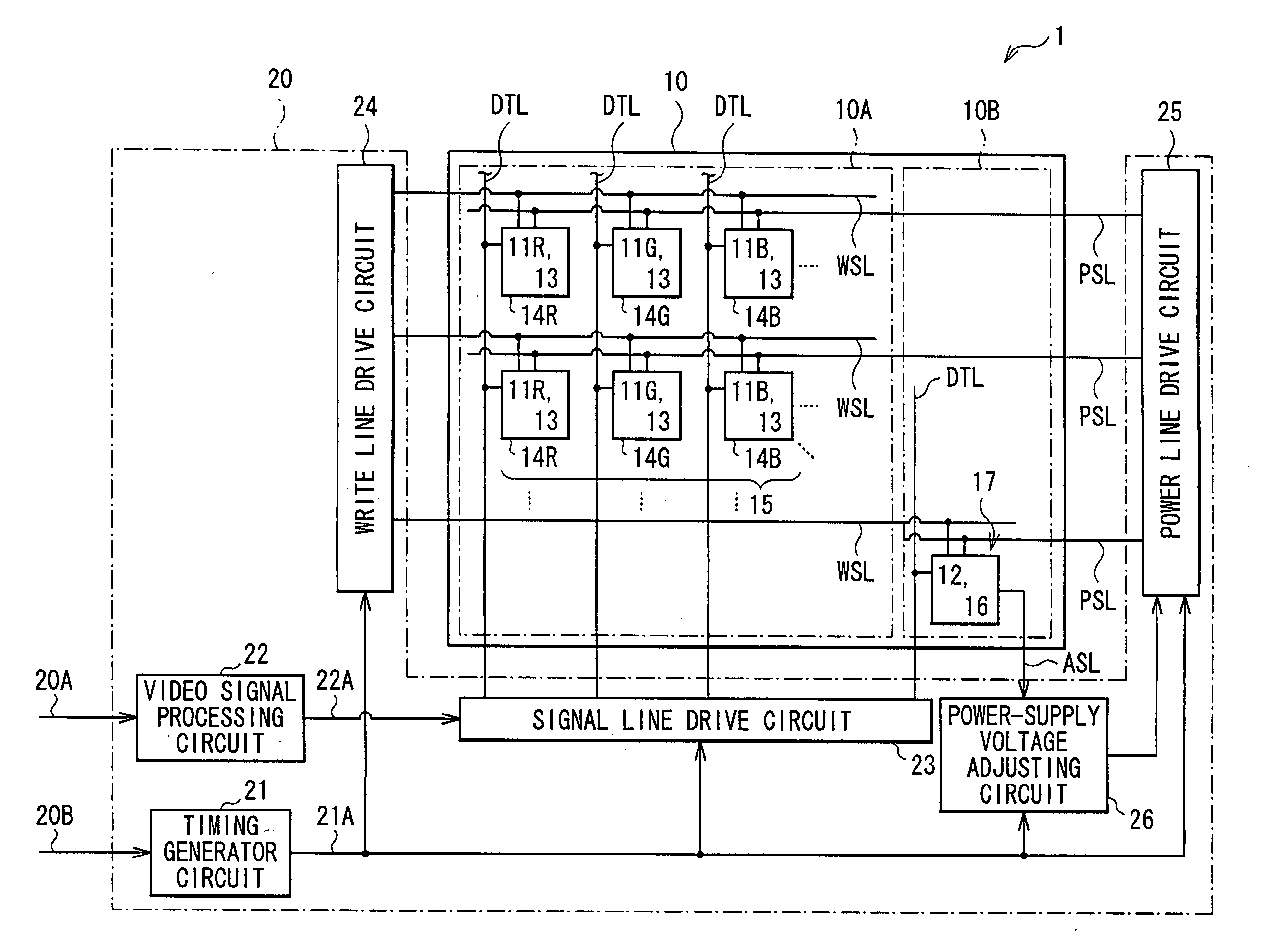
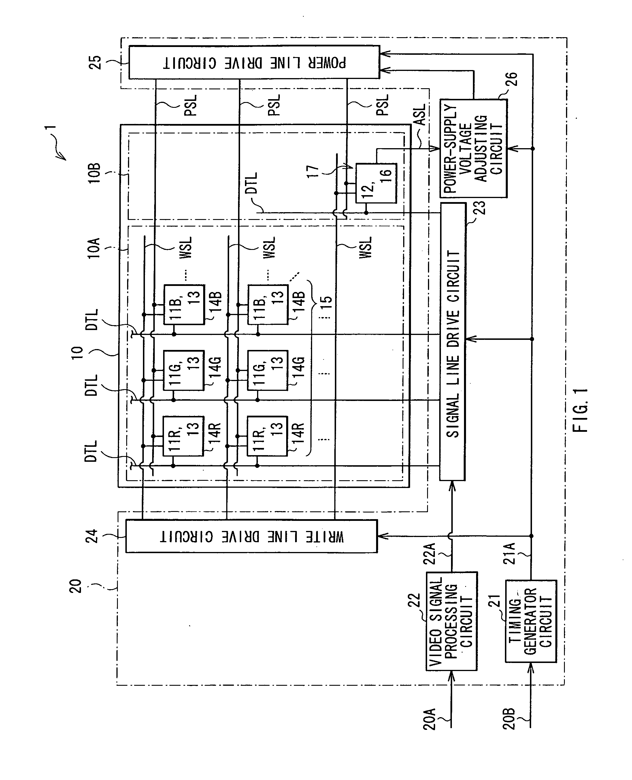
[0036]FIG. 1 shows a schematic configuration of a display device 1 according to an embodiment of the invention. The display device 1 includes a display panel 10 (display section) and a drive circuit 20 (drive section) for driving the display panel 10.

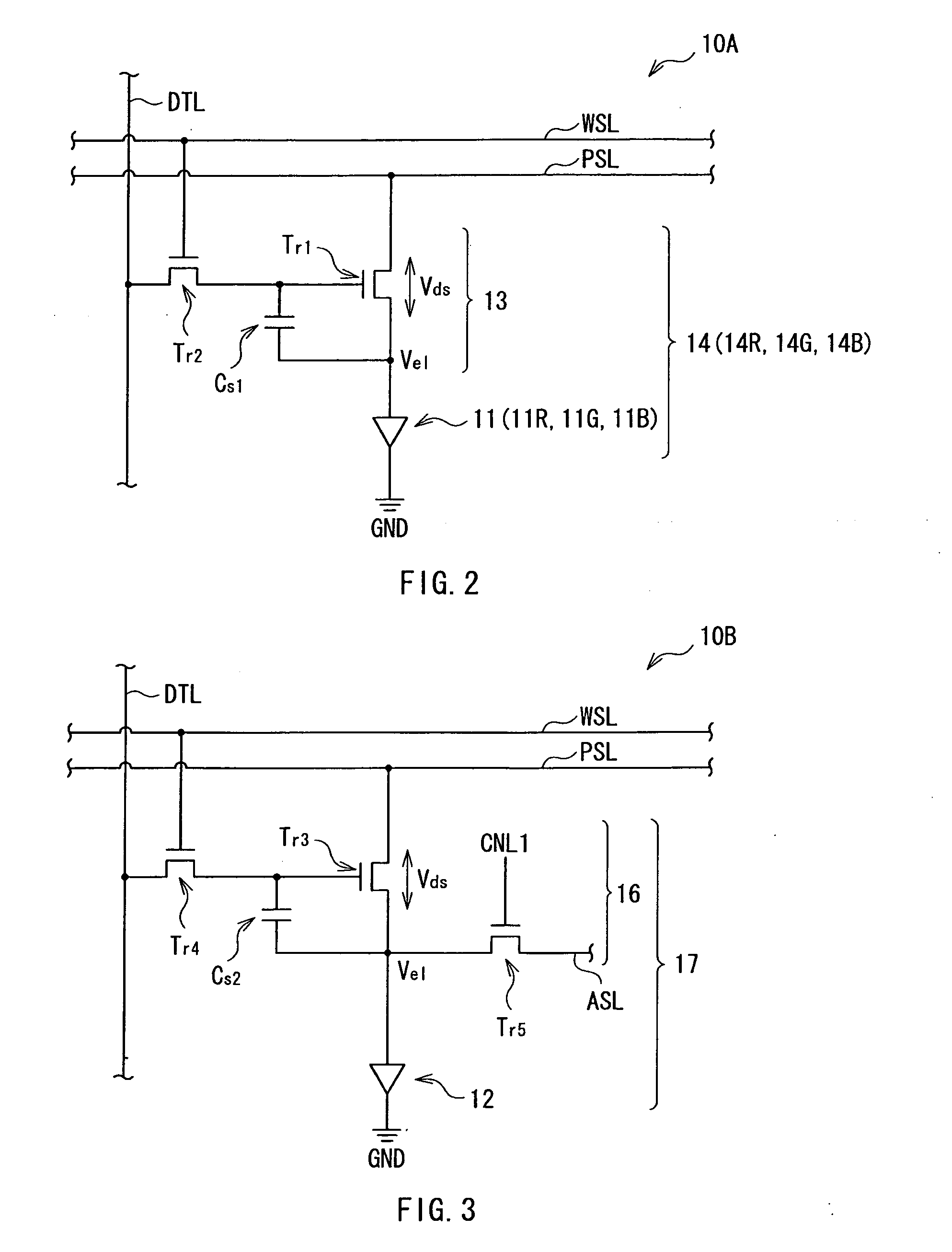
[0037]The display panel 10 has a display region 10A having a plurality of organic EL elements 11R, 11G and 11B (first light emitting elements) arranged two-dimensionally therein. Hereinafter, a term, organic EL element 11, is appropriately used as a general term of the organic EL elements 11R, 11G and 11B. The display panel 10 further has a non-display region 10B having an organic EL element 12 (second light emitting element) disposed therein. The organic EL element 12 emits light of the same emission color as that of one of the organic EL elements 11R, 11G and 11B, or emits light of a color different from emission colors of the organic EL elements 11R, 11G and 11B (for example, white light).

[0...

application examples

[0077]Hereinafter, application examples of the display device 1 described in the embodiment and the modifications thereof will be described. The display device 1 according to the embodiment and the like may be applied to display devices of electronic devices in any field for displaying a still or moving image based on an externally-inputted or internally-generated video signal, the display devices including a television apparatus, a digital camera, a notebook personal computer, a mobile terminal such as mobile phone, and a video camera.

application example 1

[0078]FIG. 13 shows appearance of a television apparatus using the display device 1 according to the embodiment and the like. The television apparatus has, for example, an image display screen 300 including a front panel 310 and filter glass 320, and the image display screen 300 is configured of the display device 1 according to the embodiment and the like.


PUM


Abstract

A display device that may be controlled to be reduced in power consumption, a method of driving the display device, and an electronic device having the display device are provided. The display device includes: a display section including a display region in which a plurality of display pixels are arranged two-dimensionally, the display pixels having first light emitting elements, and a non-display region in which one or multiple adjustment pixels are arranged, each adjustment pixel having a second light emitting element; and a drive section driving each display pixel based on a video signal, and driving the adjustment pixel based on a fixed signal. The drive section applies a power-supply voltage, having a value corresponding to voltage variation in the second light emitting element when the second light emitting element emits light, to each display pixel.

Description

BACKGROUND OF THE INVENTION[0001]1. Field of the Invention[0002]The present invention relates to a display device including a display panel having light emitting elements therein, and a method of driving the display device. In addition, the invention relates to an electronic device having the display device.[0003]2. Description of Related Art[0004]Recently, a display device using a current-drive optical element as a light emitting element in a pixel, the optical element being changed in emission luminance in accordance with a value of electric current flowing into the optical element, for example, an organic EL (Electro Luminance) element, has been developed and commercialized in a field of display devices for image display. The organic EL element is a self-luminous element unlike a liquid crystal element or the like. Therefore, a display device using the organic EL element (organic EL display device) does not need a light source (backlight) and therefore may be made small in thickn...

Claims


Application Information

Patent Timeline
IPC IPC(8): G09G5/00
CPCG09G3/3233G09G2300/0842G09G2330/028G09G2320/043G09G2330/021G09G2320/029
Inventor YAMASHITA, JUNICHIUCHINO, KATSUHIDE
Owner JOLED INC
Learn More