Ram position detection method, ram drive method, ram drive device, and press machine having the ram drive device
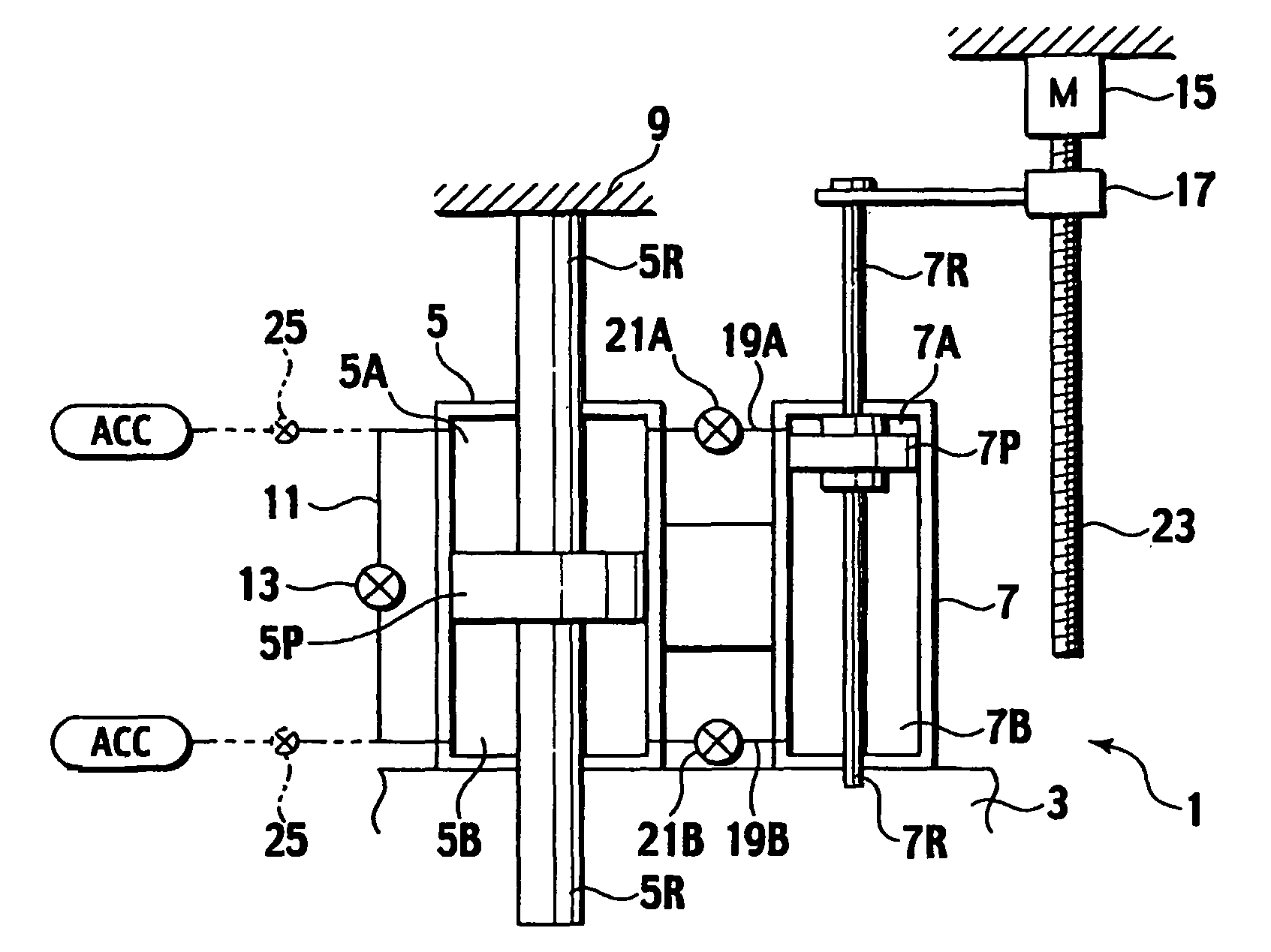
a technology of ram and position detection, which is applied in the direction of press rams, telemotors, manufacturing tools, etc., can solve the problems of limiting the increasing the length of small-diameter cylinders, and hampering the improvement of efficiency by high-speed movement of rams. achieve the effect of high degree of freedom of design
- Summary
- Abstract
- Description
- Claims
- Application Information
AI Technical Summary
Benefits of technology
Problems solved by technology
Method used
Image
Examples
second embodiment
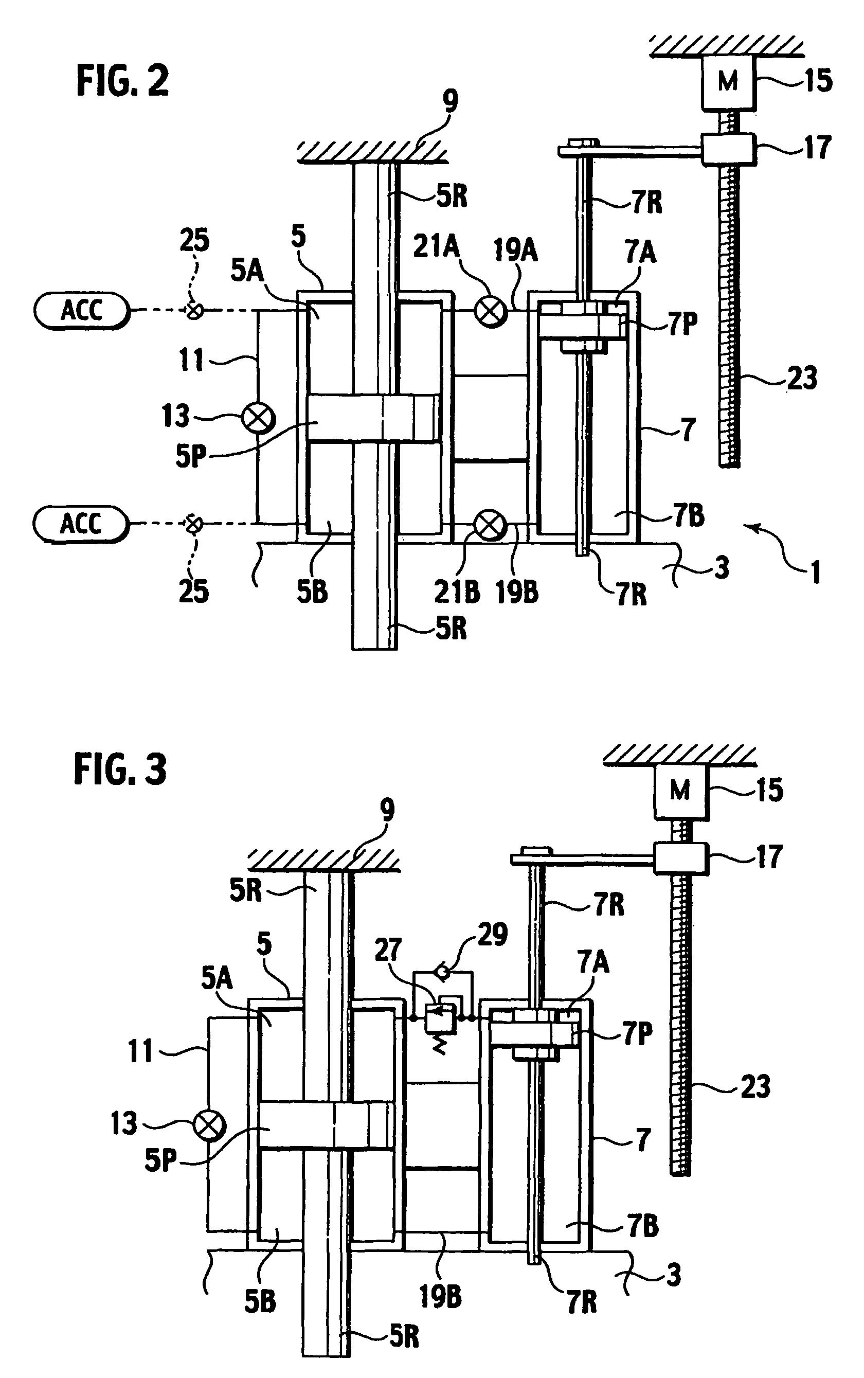
FIG. 3 shows a Constituent elements identical in function to those according to the above embodiment are denoted by like reference symbols and therefore redundant descriptions thereof will be omitted.
In the second embodiment, a press machine is configured to include a relief valve or counterbalance valve 27 on a part of the connection path 19A to permit the working fluid to flow from the first compartment 7A of the small-diameter cylinder 7 into the first compartment 5A of the large-diameter cylinder 5 when a fluid pressure in the first compartment 7A of the small-diameter cylinder 7 is equal to or higher than a pressure corresponding to the weight of the ram 3 or the like, and to include a check valve 29 arranged in parallel to the counterbalance valve 27 to permit inflow of the working fluid from the first compartment 5A into the first compartment 7A but prevent back-flow of the working fluid. Further, the press machine is configured not to include the switch valve 21B provided o...
third embodiment
FIG. 4 shows a Constituent elements identical in function to those according to the above embodiments are denoted by like reference symbols and therefore redundant descriptions thereof will be omitted.
In the third embodiment, the large and small cylinders 5 and 7 provided integrally are connected to the moving member 17 integrally and the small-diameter piston rod 7R of the small-diameter cylinder 7 is fixed to the fixing unit 9. Furthermore, the press machine is configured so that the ram 3 is provided integrally with the large-diameter piston rod 5R of the large-diameter cylinder 5 and so that the first compartment 7A and the second compartment 7B of the small-diameter cylinder 7 are connected to each other by the connection path 11.
With the above-described configuration, if the motor 15 is driven and the ball screw 23 is rotated while the on-off valve 13 provided on the connection path 11 is kept open and the switch valves 21A and 21B are kept closed, the large and small cylinde...
fourth embodiment
FIG. 5 shows a Constituent elements identical in function to those according to the above embodiments are denoted by like reference symbols and therefore redundant descriptions thereof will be omitted.
The fourth embodiment is a modified embodiment of the first embodiment described above. A diameter of a piston rod 5L on the second compartment 5B side is made larger than that of a piston rod 5S on the first compartment 5A side in the large-diameter cylinder 5, and the pressure reception area of the first compartment 5A side is made larger man that of the second compartment 5B side on the piston 5P. Further, the press machine is configured so that a pressure accumulated in the accumulator ACC always acts on the first compartment 5A.
With the above-described configuration, if the on-off valve 13 is kept open, the pressure accumulated in the accumulator ACC acts on the first and second compartments 5A and 5B of the large-diameter cylinder 5. Due to this, the internal pressure of the fir...
PUM
 Abstract
Description
Claims
Application Information
 - R&D
- Intellectual Property
- Life Sciences
- Materials
- Tech Scout
- Unparalleled Data Quality
- Higher Quality Content
- 60% Fewer Hallucinations
Browse by: Latest US Patents, China's latest patents, Technical Efficacy Thesaurus, Application Domain, Technology Topic, Popular Technical Reports.
© 2025 PatSnap. All rights reserved.Legal|Privacy policy|Modern Slavery Act Transparency Statement|Sitemap|About US| Contact US: help@patsnap.com


