
Stage apparatus and application processing apparatus

a technology of stage apparatus and application processing apparatus, which is applied in lighting and heating apparatus, drying machines with progressive movements, instruments, etc., can solve the problems of large air intake, achieve good substrate position, speed up the response to suction pressure variations, and suppress the effect of suction pressure load variations

Inactive Publication Date: 2011-03-22
TOKYO ELECTRON LTD
View PDF10 Cites 43 Cited by
  • Summary
  • Abstract
  • Description
  • Claims
  • Application Information

AI Technical Summary

Benefits of technology

This configuration maintains the substrate's levitation height and posture accurately, reducing particle attachment and power consumption, while ensuring uniform suction pressure and preventing substrate vibration, thus enabling the formation of a uniform coating film.

Problems solved by technology

Where the suction ports are arranged in this manner, however, when transferring the substrate, the plurality of gas suction ports arranged in the direction perpendicular to the substrate transfer direction are opened simultaneously and take in a large amount of air.

Method used


Image

  • Stage apparatus and application processing apparatus
  • Stage apparatus and application processing apparatus
  • Stage apparatus and application processing apparatus

Examples


Embodiment Construction

[0039]An embodiment of the present invention will be described in detail with reference to the accompanying drawing. A case will be described in which the present invention is applied to an apparatus and a method of forming a resist film on the surface of a glass substrate for an LCD (to be described as an “LCD substrate” hereinafter).

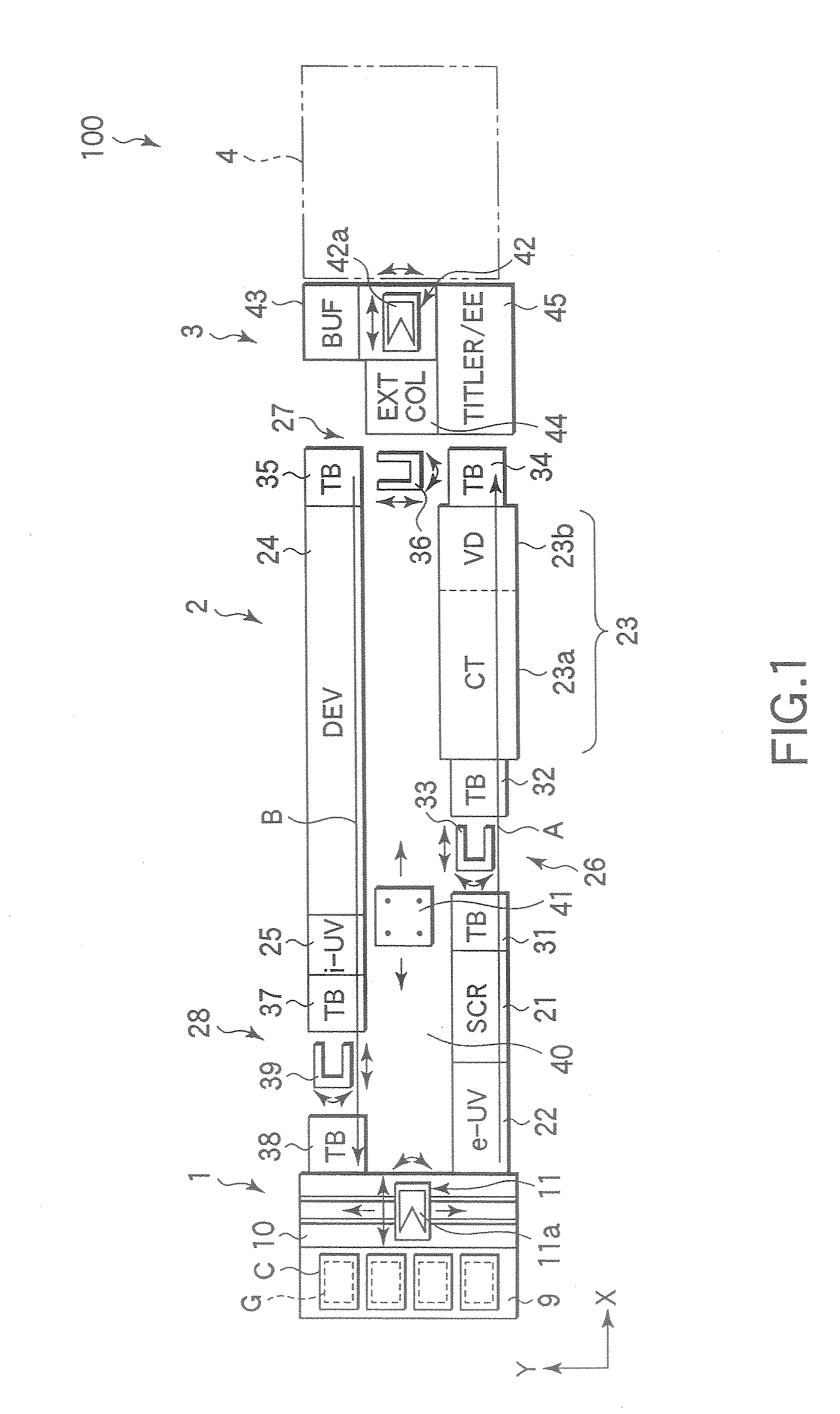
[0040]FIG. 1 is a schematic plan view of a resist coating / developing system including a resist coating unit according to one embodiment of the present invention and configured to form a resist film on an LCD substrate and develop the resist film after light exposure.

[0041]This resist coating / developing system 100 comprises a cassette station (loading / unloading portion) 1 on which cassettes C accommodating a plurality of LCD substrates G are placed, a processing station (processing portion) 2 comprising a plurality of processing units to subject the LCD substrate G to a series of processes including resist application and development, and an interface s...


PUM


Abstract

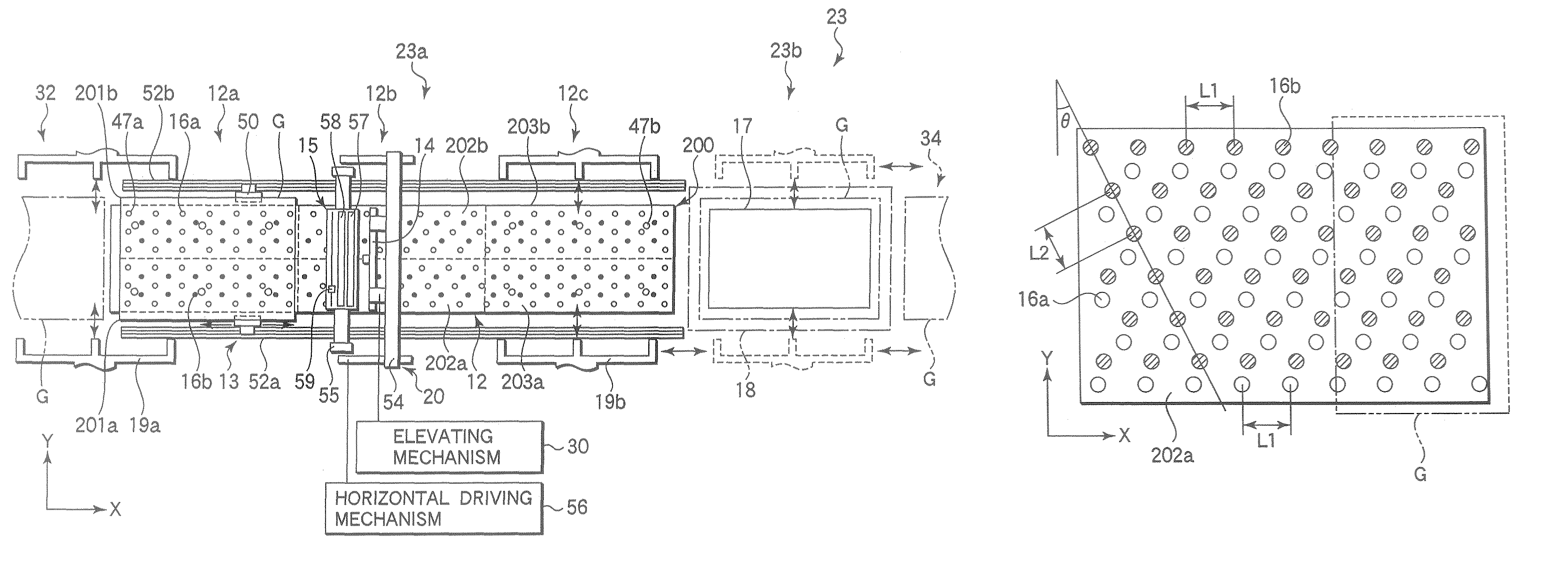
A stage apparatus in which a rectangular substrate which is levitated over a stage is transferred such that a pair of sides of the rectangular substrate are substantially parallel to a transfer direction and the other pair of sides of the rectangular substrate are substantially perpendicular to the transfer direction. The stage includes a plurality of gas spray ports to spray a gas and a plurality of suction ports to attract the rectangular substrate by suction. The rectangular substrate is levitated at a predetermined height from the surface of the stage in a substantially horizontal posture by means of suction of a suction mechanism through the plurality of suction ports and gas spray of a gas spray mechanism through the plurality of gas spray ports. The plurality of suction ports are arranged on the stage such that, when the rectangular substrate is being transferred over the stage, the leading end of the rectangular substrate in the transfer direction does not simultaneously cover not less than a predetermined number of suction ports and the trailing end of the rectangular substrate in the transfer direction does not simultaneously open not less than a predetermined number of suction ports to the atmosphere, so as for variations in suction pressure in the suction ports to fall within an allowable range.

Description

TECHNICAL FIELD[0001]The present invention relates to a stage apparatus used for transferring a substrate such as a glass substrate employed in an FPD (Flat Panel Display) such as a liquid crystal display device (LCD), and a coating system comprising the stage apparatus.BACKGROUND ART[0002]For example, in a manufacturing process for a liquid crystal display apparatus (LCD), a predetermined circuit pattern is formed on a glass substrate by using photolithography. More specifically, a resist liquid is supplied to the glass substrate to form a coating film. After drying and heat treating the coating film, a light exposure process and a developing process are successively performed.[0003]As an apparatus that supplies a resist liquid to a glass substrate to form a coating film, there is known a coating film forming system (for example, see Patent Document 1) including a stage which vacuum chucks a glass substrate horizontally, a resist supply nozzle which supplies the resist liquid to th...

Claims


Application Information

Patent Timeline
Patent Type & Authority Patents(United States)
IPC IPC(8): B05C5/02B05C13/02
CPCB65G49/065B65G49/067B65G49/068H01L21/67784B65G2249/04B65G2249/045B65G2249/02G03F7/70716G03F7/70808H01L21/677
Inventor INAMASU, TOSHIFUMIYAMASAKI, TSUYOSHIMIYAZAKI, KAZUHITO
Owner TOKYO ELECTRON LTD
Learn More