Source-measure unit based on digital control loop
a digital control loop and source-measure technology, applied in the field of measurement and data acquisition system design, can solve the problems of increasing the the decrease of achieve the effect of reducing the accuracy requirements of the dac, eliminating noise, and adding flexibility of the smu
- Summary
- Abstract
- Description
- Claims
- Application Information
AI Technical Summary
Benefits of technology
Problems solved by technology
Method used
Image
Examples
second embodiment
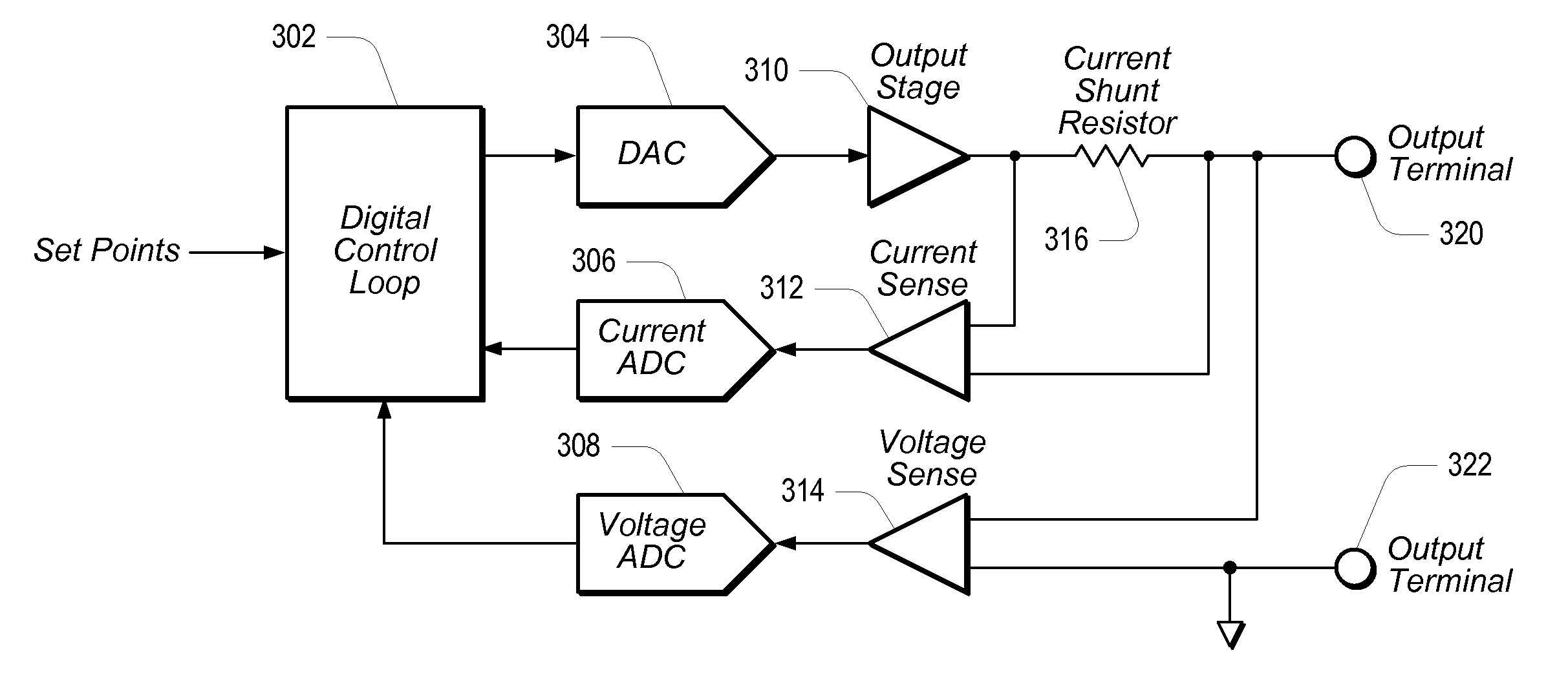
[0037]FIG. 4 shows a novel SMU in which anti-alias filtering has been added to the ADCs. As shown in FIG. 4, anti-alias filter 412 may be coupled between Current Sense element 312 and Current ADC 306, and anti-alias filter 414 may be coupled between Voltage Sense element 314 and Voltage ADC 308. Anti-alias filters 412 and 414 may operate to ensure that DCL 320 does not respond to out-of-band disturbances.
third embodiment
[0038]FIG. 5 shows a novel SMU in which shunt switching has been added in the feedback loop between the output (output terminal 320) and Current ADC 306. As shown in FIG. 5, different current shunt resistors 516 may be switched into the feedback loop between the output of Output Stage 310 and the inputs of Current Sense element 312, using a multiplexer 524 and a set of switches 518. While FIG. 5 shows three switches (518) and three current shunt resistors (516), alternate embodiments may be configured with a greater or lesser number of switches and / or resistors, as desired. Shunt switching may provide the SMU with the capability to cover a wider dynamic range of current. Any glitches that may result from switching between the various current shunt resistors may be minimized by adjusting the settings of DAC 304 simultaneously with the shunt-switching operation. Since the current is being measured and the values of the current shunt resistors (516) are known, it is possible to calcula...
fourth embodiment
[0039]FIG. 6 shows a novel SMU configured to further minimize glitches that may occur when switching between current shunt resistors 516 that have been added in the feedback loop between the output and Current ADC 306. In this case, if switches 518 happen to be slow switches, they may be operated gradually to transition between the shunt resistors (516). Current shunt resistors 516 may also be switched into the feedback loop between the output of Output Stage 310 and the inputs of a second Current Sense element 612, using additional multiplexer 624, with the output of additional Current ADC 606 be coupled back to DCL 302. Additional Current ADC 606 and additional Current Sense element 612 may be provided to make it possible to simultaneously measure the current conducted by two different current shunt resistors. Thus a reading of the total current may be obtained during the shunt-switching operation, while DCL 302 remains stable and predictable. One possible way to reduce the number...
PUM
 Abstract
Description
Claims
Application Information
 - R&D
- Intellectual Property
- Life Sciences
- Materials
- Tech Scout
- Unparalleled Data Quality
- Higher Quality Content
- 60% Fewer Hallucinations
Browse by: Latest US Patents, China's latest patents, Technical Efficacy Thesaurus, Application Domain, Technology Topic, Popular Technical Reports.
© 2025 PatSnap. All rights reserved.Legal|Privacy policy|Modern Slavery Act Transparency Statement|Sitemap|About US| Contact US: help@patsnap.com


