
Transparent conductive film and touch panel

a technology which is applied in the field of transparent conductive film and touch panel, can solve the problems of short life of touch panel, inability to use certain purposes, and low flexibility or workability, and achieve good scratch resistance

Inactive Publication Date: 2011-03-08
NITTO DENKO CORP
View PDF17 Cites 13 Cited by
  • Summary
  • Abstract
  • Description
  • Claims
  • Application Information

AI Technical Summary

Benefits of technology

The present invention provides a transparent conductive film with good scratch resistance. Additionally, the invention provides a touch panel that utilizes this transparent conductive film.

Problems solved by technology

Since the conductive glass has a glass substrate, however, it has low flexibility or workability and cannot be used for certain purposes.
However, the transparent conductive films using such film substrates have low surface scratch resistance, so that they can have problems in which they can get scratched to have an increased electrical resistance or suffer from disconnection during use.
Thus, there is a problem in which the inferior properties of the conventional transparent conductive thin layers can make the life of touch panels short.

Method used


Image

  • Transparent conductive film and touch panel
  • Transparent conductive film and touch panel
  • Transparent conductive film and touch panel

Examples


example 1

Formation of Conductive Thin Layer

[0109]A transparent conductive thin layer made of a 25 nm-thick ITO film (2.00 in refractive index) was formed on one side of a 25 μm-thick polyethylene terephthalate film (PET Film 1) by a reactive sputtering method using a sintered material composed of 90% by weight of indium oxide and 10% by weight of tin monoxide in a 4×10³ Torr atmosphere composed of 80% argon gas and 20% oxygen gas.

(Hard Coat Material)

[0110]A hard-coating material was prepared using the following materials: a urethane acrylate (hereinafter referred to as Component A) (100 parts of a urethane acrylate produced with pentaerythritol acrylate and hydrogenated xylene diisocyanate); polyol (meth)acrylate (hereinafter referred to as Component B) (49 parts of dipentaerythritol hexaacrylate (hereinafter referred to as Component B1 (monomer)), 41 parts of pentaerythritol tetraacrylate (hereinafter referred to as Component B4 (monomer)) and 24 parts of pentaerythritol triacrylate (herein...

example 2

[0114]In the process according to Example 1, 30 parts of PMMA particles (1.49 in refractive index) with an average particle size of 10 μm were added to the total amount of the resin components, when the hard coating material was prepared. A transparent conductive laminate and a touch panel were prepared using the process of Example 1, except that the resulting hard coating material was used instead.

examples 3 to 8

[0115]Transparent conductive laminates and touch panels were prepared using the process of Example 2, except that the amount of the addition of fine particles, the average particle size, and the thickness of the hard-coating layer were changed as shown in Table 1.


PUM

PropertyMeasurementUnit
thicknessaaaaaaaaaa
particle sizeaaaaaaaaaa
thicknessaaaaaaaaaa

Abstract

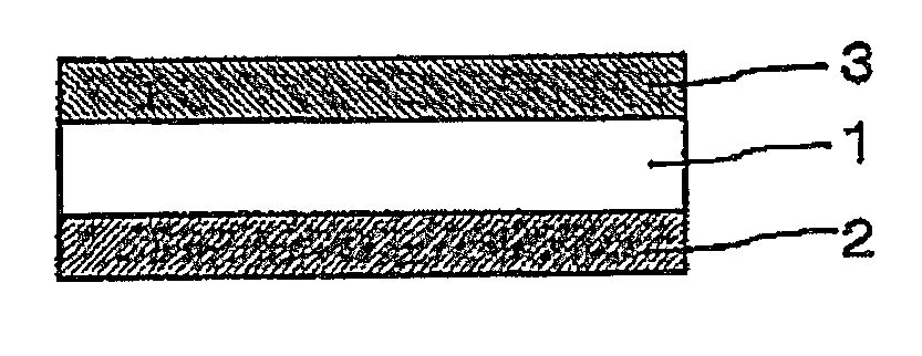
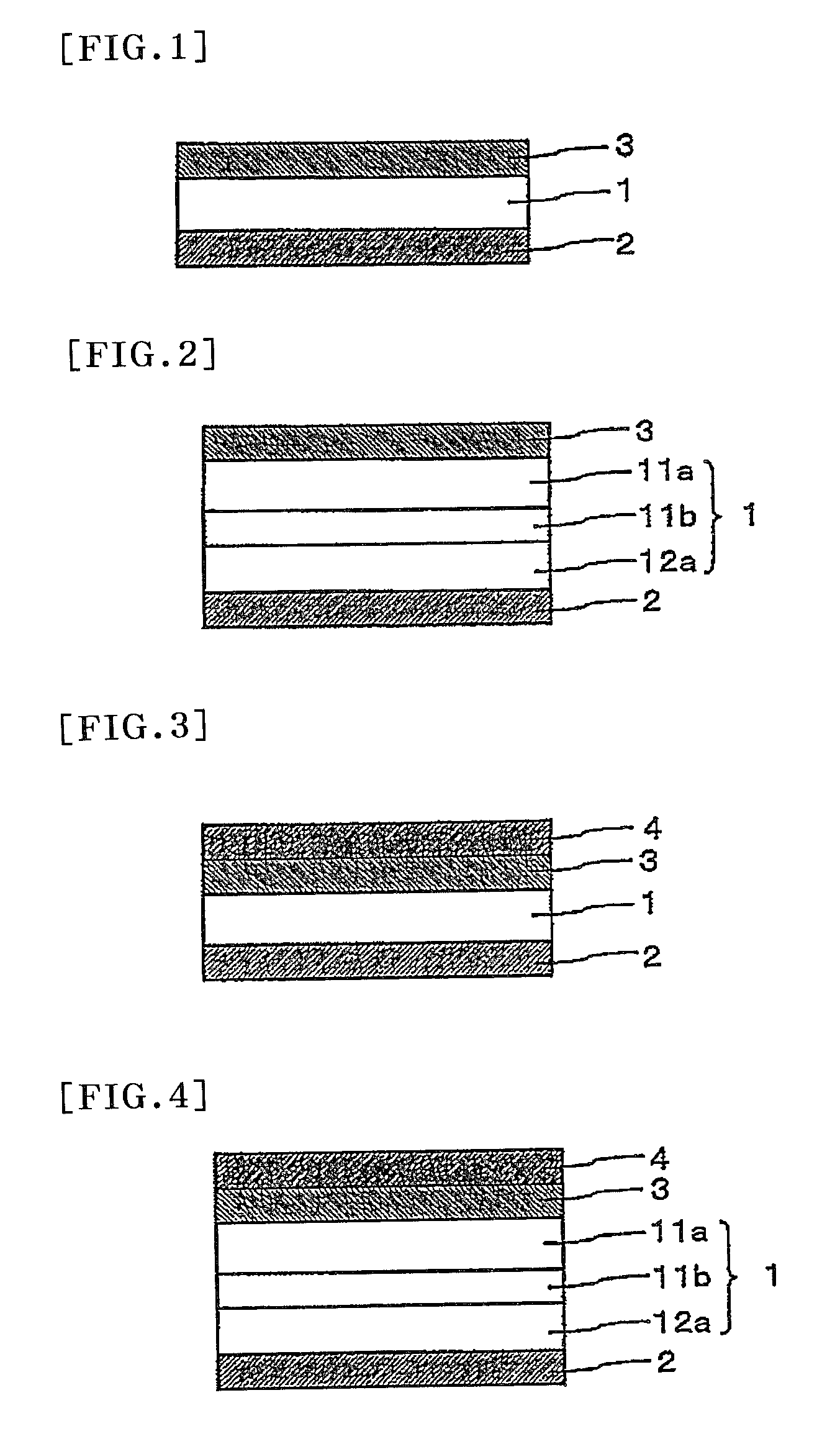
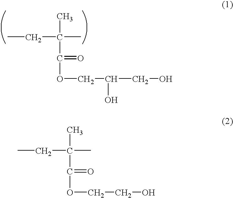
A transparent conductive film of the present invention comprises: a transparent film substrate; a hard-coating layer provided on one side of the transparent film substrate; and a transparent conductive thin layer provided on another side of the transparent film substrate, wherein the hard-coating layer is made from a material containing a urethane acrylate, a polyol (meth)acrylate and a (meth)acrylic polymer having an alkyl group containing two or more hydroxyl groups. The transparent conductive film of the present invention has good scratch resistance.

Description

TECHNICAL FIELD[0001]The present invention relates to a transparent conductive film that is transparent in the visible light region and has electrical conductivity. The present invention also relates to a touch panel using the transparent conductive film. The transparent conductive film may be used for transparent electrodes in touch panels and advanced display systems such as liquid crystal displays and electroluminescence displays and used for electromagnetic wave shielding or prevention of static charge of transparent products.BACKGROUND ART[0002]Conventionally, the so-called conductive glass is well known as a transparent conductive thin layer, which comprises a glass and an indium oxide thin layer formed thereon. Since the conductive glass has a glass substrate, however, it has low flexibility or workability and cannot be used for certain purposes. In recent years, therefore, transparent conductive films using various types of plastic films such as polyethylene terephthalate fi...

Claims


Application Information

Patent Timeline
Patent Type & Authority Patents(United States)
IPC IPC(8): C09K19/00G02F1/1335
CPCB32B27/00G06F3/045Y10T428/1059Y10T428/254C09K2323/05Y10T428/31551Y10T428/31855B32B3/30B32B7/12B32B27/08B32B27/18B32B27/28B32B27/308B32B27/40B32B33/00B32B2307/202B32B2307/412B32B2307/558B32B2309/105B32B2457/208C09D7/69G02B1/14
Inventor NOGUCHI, TOMONORITAKADA, KATSUNORITAKAO, HIROYUKIHAMAMOTO, DAISUKE
Owner NITTO DENKO CORP
Learn More