
Optical film, polarizing plate and image display device

a technology of optical film and polarizing plate, which is applied in the field of optical film, polarizing plate and image display device, can solve the problems of reducing productivity and preventing more cost reduction in the wet coating process, affecting the appearance of optical film, etc., and achieves excellent scratch resistance and anti-reflection properties. high

Inactive Publication Date: 2007-03-01
FUJIFILM CORP
View PDF4 Cites 60 Cited by
  • Summary
  • Abstract
  • Description
  • Claims
  • Application Information

AI Technical Summary

Benefits of technology

[0018] An object of the present invention is to provide an optical film assured of high antireflection property, suitability for mass production and excellent scratch resistance. Another object of the present invention is to provide a polarizing plate equipped with the optical film, and an image display device.
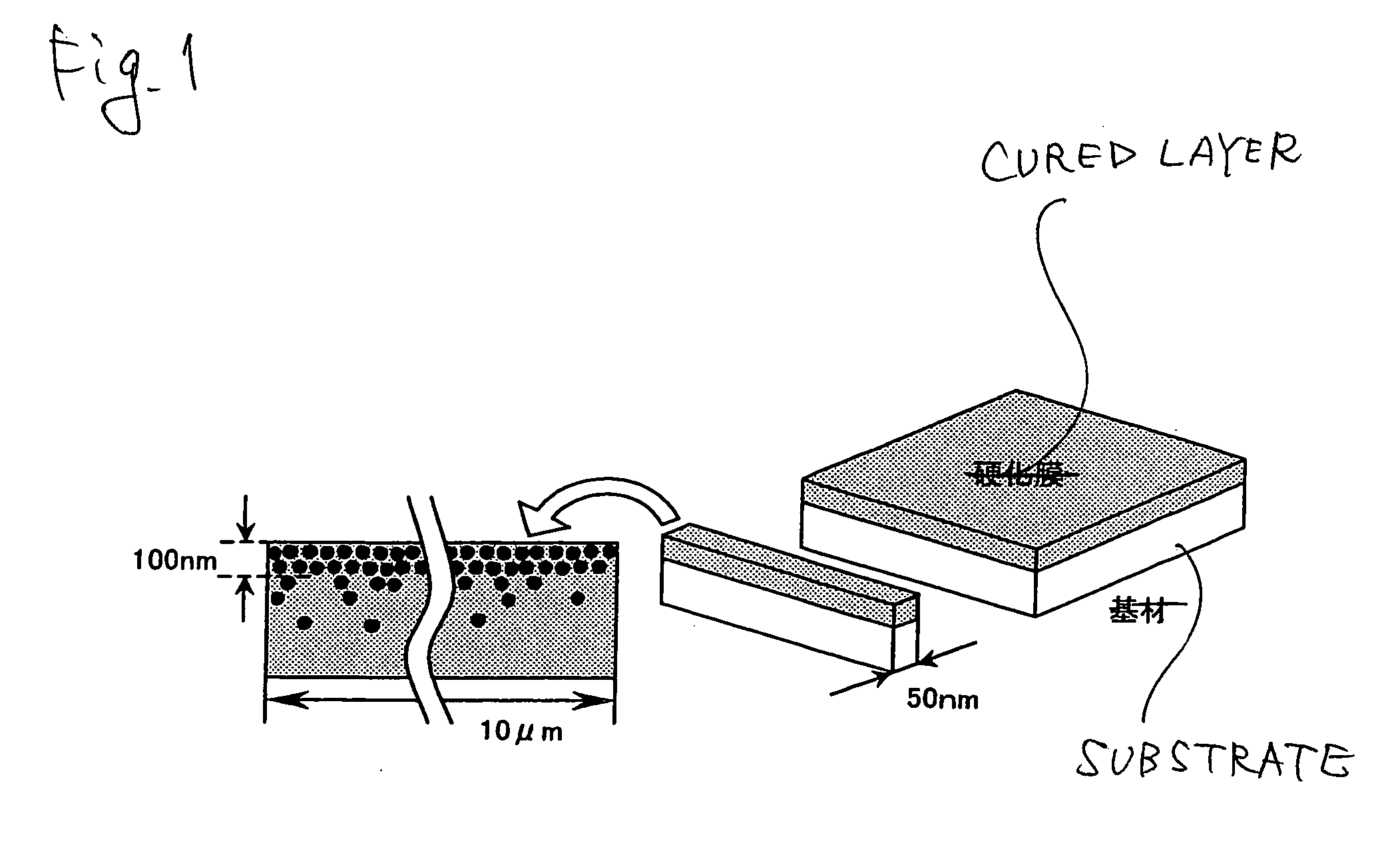
[0019] As a result of intensive investigations, the present inventors have found that when a curable composition containing a low refractive index fine particle reduced in the surface free energy by chemical surface modification is coated on a transparent plastic film substrate and the low refractive index fine particle is caused to rise to the surface of the coated layer until curing, an antireflection layer and a hardcoat layer can be formed at the same time, and an antireflection hardcoat film assured of high antireflection property, suitability for mass production and excellent scratch resistance can be prepared.

Problems solved by technology

Therefore, when an antireflection film is prepared by using a wet coating process, the operation of coating, drying and curing a curable composition needs to be repeated at least twice or more, and this extremely reduces the productivity and impedes more cost reduction in the wet coating process.
In addition, this coating system is a method of curing an underlying layer and then stacking an uncured layer thereon and since the underlying layer is already immobilized by curing and the reactive group in the underlying layer is already consumed at the curing, chemical bonding to a layer thereon can be hardly established and interlayer adhesion may not be ensured.
As described above, the requirement for scratch resistance is rapidly increasing in recent years and it is a very important issue to ensure interlayer adhesion and thereby obtain high scratch resistance.
However, in the case of forming a coating film from a photoradical curing-type resin, nitrogen purging must be performed twice and unless this point is improved, the problem remains in the interlayer adhesion from the aspect of performance, because such a coating system is still a coating method of stacking the layers one by one.
However, the surface low refractive index layer formed of a fluorine compound has poor cohesive strength and cannot be assured of scratch resistance corresponding to surface chipping resistance which can be evaluated by a steel wool rubbing test or the like.
Moreover, the cured film obtained is a thin film having a thickness of 1 μm or less and cannot be assured of surface indentation hardness which can be evaluated by a pencil hardness test or the like, and sufficiently high scratch resistance cannot be obtained.
However, the layer formed by one coating operation is only a low refractive index layer and in the case of providing a plurality of functional layer species by coating, the improvement effect for the enhancement of productivity is not provided.
In order to obtain an antireflection film having high surface hardness, the inorganic fine particle having a high specific gravity must be caused to rise to the surface rather than the coating solution, and this method cannot be applied.
However, these publications are absolutely silent on the application to an antireflection film and the continuous production of the film.
However, this method has a problem such that the particle size of 50 to 450 nm is too large to cause migration of the particle to the surface or even if a particle having a particle diameter of 50 to 450 nm is present inside the cured layer, sufficiently high antiglare property cannot be obtained because of its small particle diameter.
However, for obtaining an antireflection film by this method, a low refractive index layer needs to be further stacked.

Method used


Image

  • Optical film, polarizing plate and image display device
  • Optical film, polarizing plate and image display device
  • Optical film, polarizing plate and image display device

Examples


example 1-1

[0282] A 1,340 mm-wide and 2,600 m-long triacetyl cellulose film, “TD80U” {produced by Fuji Photo Film Co., Ltd.}, in a roll form was unrolled as the support (substrate), and Coating Solution (HCL-1) for Hardcoat Layer, where surface-modified low refractive index fine particles were added, was coated directly thereon by using a doctor blade and a 50 mm-diameter microgravure roll having a gravure pattern with a line number of 135 lines / inch and a depth of 60 μm, under the condition of a transportation speed of 15 m / min and after drying at 60° C. for 150 seconds, irradiated with an ultraviolet ray at an illumination intensity of 400 mW / cm2 and an irradiation dose of 250 mJ / cm2 by using an air-cooled metal halide lamp of 160 W / cm (manufactured by Eye Graphics Co., Ltd.) while purging the system with nitrogen to keep an oxygen concentration of 1.0 vol % or less, thereby curing the coated layer and forming Hardcoat Layer (HC-1). The resulting film was taken up. After the curing, the rota...

example 1-3

[0284] A 1,340 mm-wide and 2,600 m-long triacetyl cellulose film, “TD80U” {produced by Fuji Photo Film Co., Ltd.}, in a roll form was unrolled as the support (substrate), and Coating Solution (HCL-4) for Hardcoat Layer, where surface-modified low refractive index fine particles were added, was coated directly thereon by using a doctor blade and a 50 mm-diameter microgravure roll having a gravure pattern with a line number of 135 lines / inch and a depth of 60 μm, under the condition of a transportation speed of 15 m / min and after drying at 70° C. for 150 seconds, irradiated with an ultraviolet ray at an illumination intensity of 400 mW / cm2 and an irradiation dose of 250 mJ / cm2 by using an air-cooled metal halide lamp of 160 W / cm (manufactured by Eye Graphics Co., Ltd.) while purging the system with nitrogen to keep an oxygen concentration of 1.0 vol % or less, thereby curing the coated layer and forming Hardcoat Layer (HC-4). The resulting film was taken up. After the curing, the rota...

example 2-1

[0285] A 1,340 mm-wide and 2,600 m-long triacetyl cellulose film, “TD80U” {produced by Fuji Photo Film Co., Ltd.}, in a roll form was unrolled as the support (substrate), and Coating Solution (HCL-5) for Antiglare Hardcoat Layer, where surface-modified low refractive index fine particles were added, was coated directly thereon by using a doctor blade and a 50 mm-diameter microgravure roll having a gravure pattern with a line number of 135 lines / inch and a depth of 60 μm, under the condition of a transportation speed of 15 m / min and after drying at 60° C. for 150 seconds, irradiated with an ultraviolet ray at an illumination intensity of 400 mW / cm2 and an irradiation dose of 250 mJ / cm2 by using an air-cooled metal halide lamp of 160 W / cm (manufactured by Eye Graphics Co., Ltd.) while purging the system with nitrogen to keep an oxygen concentration of 1.0 vol % or less, thereby curing the coated layer and forming Antiglare Hardcoat Layer (HC-5). The resulting film was taken up. After ...


PUM


Abstract

An optical film comprises: a transparent plastic film substrate; and a cured layer having a dry thickness of 100 nm or more, formed by coating a curable composition comprising: a low refractive index fine particle having a refractive index of 1.50 or less; and a binder, wherein the low refractive index fine particle is unevenly distributed in the cured layer to a surface portion on the side opposite the transparent plastic film substrate.

Description

BACKGROUND OF THE INVENTION [0001] 1. Field of the Invention [0002] The present invention relates to an optical film formed by unevenly distributing a low refractive index fine particle, a polarizing plate using this optical film, and an image display device. More specifically, the present invention relates to an antireflection hardcoat film formed from a curable composition comprising a surface-modified low refractive index fine particle and a curable resin, a polarizing plate using the same, and an image display device. [0003] 2. Description of the Related Art [0004] In various image display devices such as liquid crystal display device (LCD), plasma display panel (PDP), electroluminescence display (ELD) and cathode ray tube display device (CRT), an antireflection film is disposed on the display surface for preventing reduction in the contrast due to reflection of outside light or projection of an image. Accordingly, the antireflection film is required to have high transmittance a...

Claims


Application Information

Patent Timeline
Patent Type & Authority Applications(United States)
IPC IPC(8): G02B1/10
CPCG02B1/111G02B5/0242G02B5/3033G02B5/0294G02B5/0278
Inventor FUKUDA, KENICHIWATANABE, JUN
Owner FUJIFILM CORP
Learn More