Correction of troposphere induced errors in global positioning systems

a global positioning system and troposphere technology, applied in the field of global positioning system correction of troposphere induced errors, can solve the problems of inability to accurately model, difficulty in simple modeling of tropospheric delays, and cost in computation and time taken to determine the location

Inactive Publication Date: 2011-01-25
THE SEC OF STATE FOR DEFENCE IN HER BRITANNIC MAJESTYS GOVERNMENT OF THE UK OF GREAT BRITAIN & NORTHERN IRELAND
View PDF5 Cites 3 Cited by
  • Summary
  • Abstract
  • Description
  • Claims
  • Application Information

AI Technical Summary

Problems solved by technology

The existing systems have been progressively refined so that using a differential phase implementation a locational accuracy of less than 2 cm can potentially be achieved over a baseline of 1000 km, but with a cost in computation and in the time taken to determine the location.
However, whether the user is interested in obtaining a position or a time measurement, a significant error arises from the inability to model accurately the delay to the GNSS signals caused by the atmosphere, namely the ionosphere and troposphere.
However, the troposphere constitutes one of the largest identified sources of error in the effect that it has on signals propagating therethrough.
Tropospheric delays are difficult to model simply.
However, although these models permit incorporation into a user receiver they are inherently limited in ability to accommodate changes in tropospheric conditions that affect signal delays caused by the constantly cha...

Method used


Image

  • Correction of troposphere induced errors in global positioning systems
  • Correction of troposphere induced errors in global positioning systems
  • Correction of troposphere induced errors in global positioning systems

Examples


Embodiment Construction

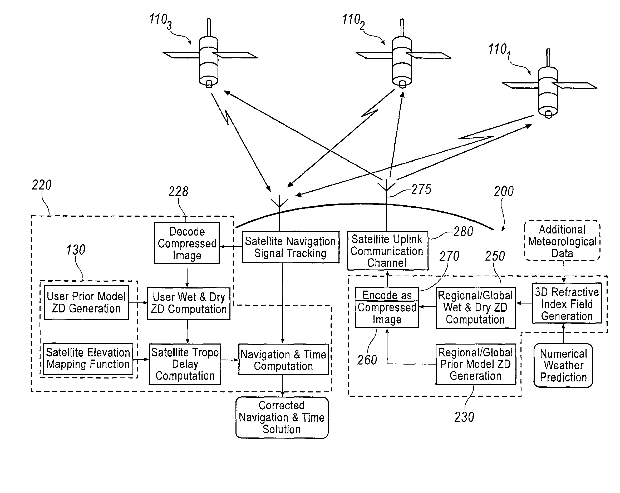
[0058]Referring to FIG. 1 this represents in schematic form a section of the earths surface 50 and in relation thereto a global positioning system 100 comprising a plurality of GNSS satellites 1101, 1102, 1103, . . . in earth orbit and a user 120, in the form of a signal receiver and processor of hand-held or vehicle-mounted type at or above the earth's surface.

[0059]The user receiver 120 comprises, in conventional manner, a front end receiver 122 of signals transmitted from the various satellites within view at radio frequency frequencies, processing means 124 and information display or like delivery apparatus 126. The processing means includes a digital processor that responds to received signals from, and characteristic of, the various satellites whose orbital positions are known with respect to points on the earth and computes from the variations in reception of these signals a solution comprising the position of the user receiver in two- or three-dimensions, and, importantly in...


PUM


Abstract

A method of obtaining data for use by a receiver of a satellite positioning system or a GNSS comprises deriving the data remotely from the receiver by a server (200), using meteorological information and a regional or global three dimensional map of grid points from which it computes tropospherical delays by ray tracing through the refractivity field derived from atmospheric measurements of pressure, temperature and water data content, such measurements being available from meteorological bodies. When used to enhance position determined by a user receiver that includes a non-meteorological, climate based model (130) giving zenith delays and means (130′) to map them to particular inclinations, the server also includes a copy of such non-meteorological model (230) and provides its ray traced delay values as zenith delays. The sets of zenith delay values for corresponding grid points are compared in the server (260) and modifications developed (preferably in fractional form) by which the non-meteorological delay values require correcting to be accurate. The correction sets are reduced by image compression techniques (270) and transmitted via the satellites (1101 etc) of the GNSS at low data rate to the user receiver, which receiver simply applies the corrections to the Zenith delays derived by its own model. If a user position is known, the server may derive accurate tropospheric delay values directly for the receiver position directly for transmission.

Description

FIELD OF THE INVENTION[0001]The present invention relates to developments intended to increase the accuracy obtainable from global navigation satellite systems (GNSS).BACKGROUND OF THE INVENTION[0002]At present there are two publicly available GPS systems, known as NAVSTAR, owned by the USA, and GLONASS owned by the Russian Federation. These have been in existence for around two decades, but in the near future it is hoped that the European regional augmentation of GPS will start to provide its services, followed within a few years by a European system under the name of GALILEO.[0003]The existing systems have been progressively refined so that using a differential phase implementation a locational accuracy of less than 2 cm can potentially be achieved over a baseline of 1000 km, but with a cost in computation and in the time taken to determine the location. Real time or near real time measurements have a correspondingly lower resolution, and at present the requirements for high preci...

Claims


Application Information

Patent Timeline
IPC IPC(8): G01S5/00G01S1/00G01S5/02G01S19/07G01S19/05G01S19/10G01S19/40G01S19/41
CPCG01S5/009G01S19/07G01S19/40G01S19/41G01S19/071
Inventor POWE, MATTHEW DUNCANBUTCHER, JAMESOWEN, JOHN IFOR REWBRIDGE
Owner THE SEC OF STATE FOR DEFENCE IN HER BRITANNIC MAJESTYS GOVERNMENT OF THE UK OF GREAT BRITAIN & NORTHERN IRELAND
Why Eureka
Try Eureka