Semiconductor device, display device and electronic device equipped with the semiconductor device
a technology of semiconductor devices and display devices, applied in static indicating devices, organic semiconductor devices, instruments, etc., can solve the problems of difficulty in realizing a large and high luminance display device or the like, luminance variation, luminance variation, etc., to achieve low power consumption, prevent current, and high aperture ratio
- Summary
- Abstract
- Description
- Claims
- Application Information
AI Technical Summary
Benefits of technology
Problems solved by technology
Method used
Image
Examples
embodiment mode 1
[0166]The present invention can be applied to not only a pixel including an EL element but also various analog circuits including a current source. First, in this embodiment mode, description is made of a basic principle of the present invention.
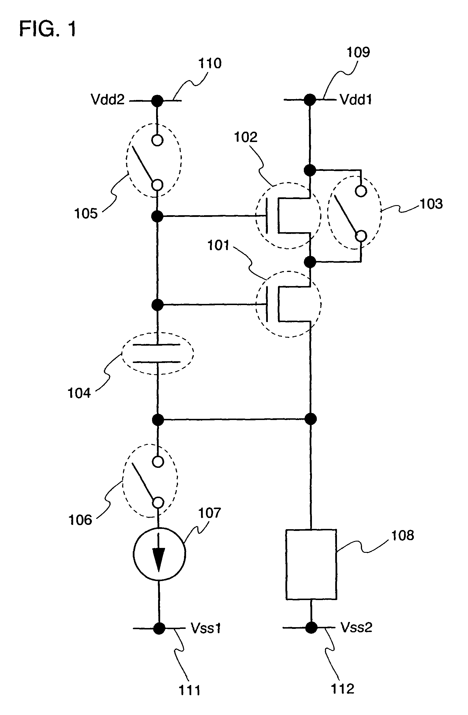
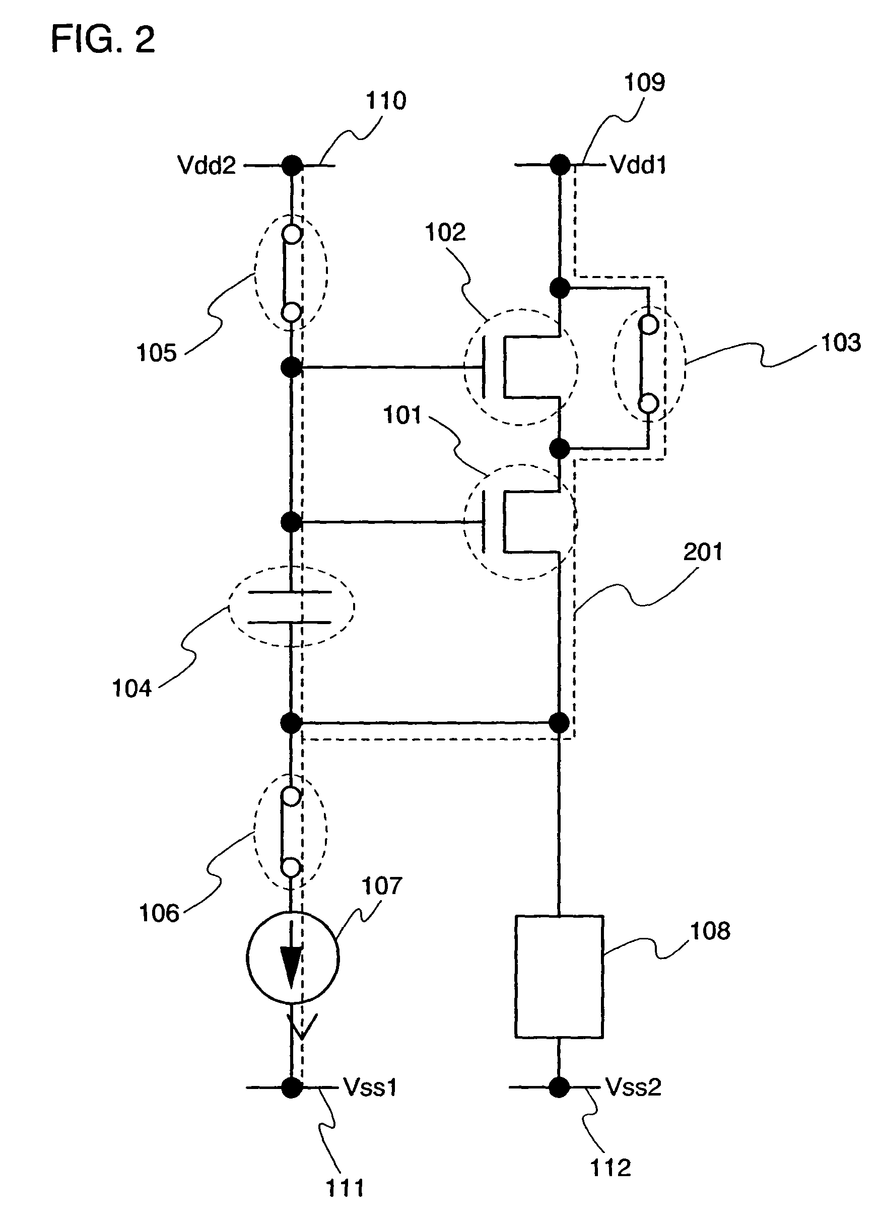
[0167]FIG. 1 shows a configuration based on the basic principle of the present invention. There are provided a transistor 101 which always serves as a current source (or a part of a current source) (hereinafter, also referred to as a first transistor or a current source transistor) and a transistor 102 which operates differently depending on a state (hereinafter also referred to as a second transistor or a shift transistor). The current source transistor 101, the shift transistor 102 and a wire 109 are connected in series. A gate of the current source transistor 101 is connected to one terminal of a capacitor element 104. The other terminal of the capacitor element 104 is connected to a source terminal of the current source transistor 101. T...
embodiment mode 2
[0200]In Embodiment Mode 2, a configuration different from the analog circuit of FIG. 1 will be described.
[0201]FIG. 7 shows an example in which the connection of the switch 103 in FIG. 1 is changed. The switch 103 is connected to a wire 702. A potential of the wire 702 is supplied with Vdd3 which is higher than Vdd1.
[0202]An operation of FIG. 7 is described briefly. As shown in FIG. 8, switches 103, 105 and 106 are turned ON, and a switch 701 is turned OFF. A current path at that time is schematically shown by a broken line with an arrow 801. No current flows between a source and a drain of a shift transistor 102, and a current flows to a current source transistor from the switch 103. When the current flowing between the source and the drain of the current source transistor 101 is equal to the current Ib flowing to the current source 107, no current flows to the capacitor element 104. In other words, a steady state is obtained. At that time, a gate potential of the current source t...
embodiment mode 3
[0215]In Embodiment Mode 3, a configuration different from the analog circuits of the above embodiment modes will be described.
[0216]In FIG. 1, the current source transistor 101 and the shift transistor 102 are both N-channel transistors. In this embodiment mode, a case is described, where the current source transistor 101 and the shift transistor 102 are both P-channel transistors. As for the circuit of FIG. 1, FIG. 12 shows an example in the case where the polarity (conductivity) of the current source transistor 101 and the shift transistor 102 are changed and the connection structure of the circuit is not changed. When FIG. 1 and FIG. 12 are compared, it is apparent that the change is easily done by changing potentials of the wires 109, 110, 111 and 112 to the ones of wires 1209, 1210, 1211 and 1212, and by changing the direction of current of a current source 1207. The connections of a current source transistor 1201, a shift transistor 1202, switches 1203, 1205, and 1206, the cu...
PUM
 Abstract
Description
Claims
Application Information
 - R&D
- Intellectual Property
- Life Sciences
- Materials
- Tech Scout
- Unparalleled Data Quality
- Higher Quality Content
- 60% Fewer Hallucinations
Browse by: Latest US Patents, China's latest patents, Technical Efficacy Thesaurus, Application Domain, Technology Topic, Popular Technical Reports.
© 2025 PatSnap. All rights reserved.Legal|Privacy policy|Modern Slavery Act Transparency Statement|Sitemap|About US| Contact US: help@patsnap.com


