
Ceramic with improved high temperature electrical properties for use as a spark plug insulator

a high temperature electrical and insulator technology, applied in spark plugs, basic electric elements, electrical equipment, etc., can solve the problems of degrading degrading the components of the spark plug, and the spark may not reliably jump, so as to improve the quality of the spark, improve the shunt resistance and dielectric breakdown properties, and reduce the shunting of the spark plug

Inactive Publication Date: 2010-12-28
FEDERAL MOGUL WORLD WIDE LLC
View PDF41 Cites 4 Cited by
  • Summary
  • Abstract
  • Description
  • Claims
  • Application Information

AI Technical Summary

Benefits of technology

The incorporation of P2O5 or B2O3 increases dielectric strength by up to 5% and shunt resistance by up to 200%, resulting in a ceramic insulator that is less susceptible to breakdown, maintaining high performance over extended periods at high temperatures and voltages.

Problems solved by technology

Unfortunately, the high voltage and high temperature environment within the combustion chamber can degrade components of the spark plug.
As the spark plug becomes degraded, the intensity of the ignition pulse may become altered, thereby degrading the quality of the spark.
Degradation of the spark plug may be caused by dielectric puncture through the insulator which establishes an alternative electric path and consequently the spark may not reliably jump the gap between the center and ground electrodes.
The quality of the spark effects the ignition of the mixture of the air and fuel (i.e., the combustion efficiency, combustion temperature, combustion products) thus, the power output, fuel efficiency performance of the engine, and the emissions produced by the combustion of the air and fuel may be adversely affected.
Any leakage of current leads to localized heating which gradually degrades the resistance of the material to dielectric puncture.
It has been observed that resistance of insulators to dielectric breakdown tends to decrease over the life of a spark plug due to thermal stress on the spark plug cycling under an applied electric field and due to attendant thermal-electrical fatigue thereof.
Whereas dielectric breakdown tends to be a sudden event, shunt resistance tends to be a continuous, parasitic loss of electrical power.
Of course, the lower the shunt resistance, the higher the likelihood of catastrophic dielectric failure after the spark plug.
However, in the case of shunting caused by diminished or insufficient shunt resistance, the affect is may simply degrade the spark performance.
This additional path even if very small has an adverse effect on the quality of the spark generated by the spark plug.
Whereas the parallel electric path is generally due to dielectric breakdown, the effect is generally catastrophic and in many cases significantly reducing or completely eliminating the spark between the center electrode and the ground electrode.
A diminished or insufficient shunt resistance degrades the performance of the spark plug and consequently the performance of the engine especially over the service lifetime of the spark plug.
As stated above, many times, a degraded shunt resistance will eventually cause a catastrophic failure due to dielectric loss.
Currently, the size the spark plug is limited from further reduction due to the required dielectric strength of the insulator over the service lifetime of the plug, which is directly related to the thickness required for the walls of the insulator.
Another factor limiting size reduction is that more manufacturers are demanding a longer service lifetime from spark plugs such as requesting 100,000 mile, 150,000 mile, and 175,000 mile service lifetimes from spark plugs.
However, the current demand for more compact spark plugs for modern engines prevents or limits the use of thicker walled insulators.

Method used


Image

  • Ceramic with improved high temperature electrical properties for use as a spark plug insulator
  • Ceramic with improved high temperature electrical properties for use as a spark plug insulator
  • Ceramic with improved high temperature electrical properties for use as a spark plug insulator

Examples


Embodiment Construction

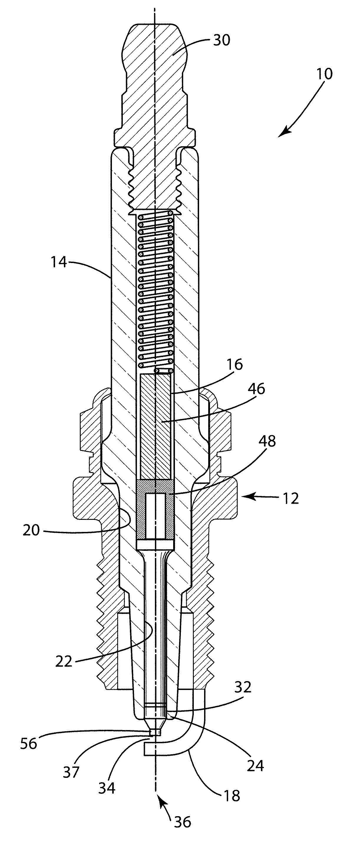
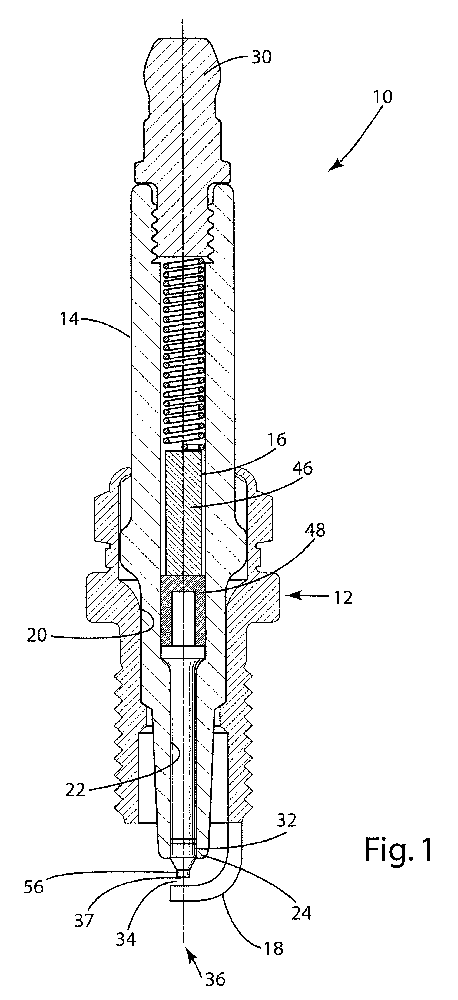
[0033]The present invention relates generally to ignition devices for high temperature applications, such as spark plugs, igniters and other spark generation devices. With reference to FIG. 1, there is shown an ignition device comprising a spark plug assembly 10 for use in an internal combustion engine (not shown) that generally includes a metal shell 12, a ceramic insulator 14, a center wire assembly 16, and a ground electrode 18. As commonly known in the art, the shell 12 is a generally cylindrical, electrically conductive component having a hollow bore 20 extending along its axial length. Within that bore 20 are a series of circumferential shoulders sized to support diametrically reduced sections of the insulator 14. Like the shell 12, the insulator 14 is also a generally cylindrical component with an elongated axial bore 22. The lower axial end of the insulator 14 comprises a nose portion 24 which generally extends out of and beyond the lowermost portion of the shell 12. The ins...


PUM

PropertyMeasurementUnit
temperatureaaaaaaaaaa
voltageaaaaaaaaaa
operating temperatureaaaaaaaaaa

Abstract

An insulator including alumina in an amount between about 90 and about 99% by weight and an oxide mixture or glass mixture including Boron Oxide, Phosphorus Oxide, or both Boron and Phosphorus Oxide.

Description

CROSS-REFERENCE TO RELATED PATENT APPLICATIONS[0001]This application is a continuation-in-part of U.S. patent application Ser. No. 10 / 984,135, filed on Nov. 9, 2004, now U.S. Pat. No. 7,169,723 which claims priority to U.S. Provisional Patent Application Ser. No. 60 / 519,395, filed on Nov. 12, 2003, each of which are hereby incorporated herein by reference in their entirety.BACKGROUND OF THE INVENTION[0002]1. Technical Field[0003]The present invention generally relates to ceramic materials. More particularly, it relates to ceramic materials used in insulators of spark plugs.[0004]2. Related Art[0005]Spark plugs, glow plugs, and other such devices used in internal combustion engines are subjected to high temperature environments in the region of about 1,000° C. In general, a spark plug is a device that extends into a combustion chamber of an internal combustion engine and produces a spark to ignite a combustible mixture of air and fuel therein. Specifically, a spark plug typically inc...

Claims


Application Information

Patent Timeline
Patent Type & Authority Patents(United States)
IPC IPC(8): C04B35/111H01T13/38C04B35/117C04B35/119
CPCC04B35/117C04B35/119C04B35/62655H01T13/38C04B2235/3201C04B2235/3203C04B2235/3206C04B2235/3208C04B2235/321C04B2235/3213C04B2235/3215C04B2235/3217C04B2235/3244C04B2235/3418C04B2235/3445C04B2235/3454C04B2235/349C04B2235/36C04B2235/72C04B2235/727C04B2235/80C04B35/10H01T13/20
Inventor WALKER, JR., WILLIAM JOHNHOFFMAN, JOHN WILLIAM
Owner FEDERAL MOGUL WORLD WIDE LLC
Learn More