
Method and system to attach carbon nanotube probe to scanning probe microscopy tips

a carbon nanotube and microscopy tip technology, applied in the field of nanotubes, can solve the problems of easy damage or wear of the tip, the tip diameter of the scanning probe is generally greater than 10 nm, and the silicon probe is easy to be damaged or worn during use, and achieves excellent mechanical stability and easy control.

Inactive Publication Date: 2010-12-07
UNIV OF CENT FLORIDA RES FOUND INC
View PDF29 Cites 7 Cited by
  • Summary
  • Abstract
  • Description
  • Claims
  • Application Information

AI Technical Summary

Benefits of technology

"The present invention provides a method and system for attaching novel nanotube probes to scanning probe microscope tips using Focus Ion Beam (FIB) technology. This allows for easy and controllable attachment of carbon nanotubes to the tips, providing improved mechanical stability. The method involves preparing a novel nanotube probe by catalytic chemical vapor deposition, aligning it within a slot in the scanning probe tip using a micro manipulator, and then using FIB welding to deposit metal atoms to fill the gap between the carbon fiber and the wall of the slot, resulting in a secure attachment of the carbon fiber with nanotube tip and the scanning probe cantilever tip. The technical effects of this invention include improved precision and accuracy in scanning probe microscopy and related applications."

Problems solved by technology

Silicon probes are commonly used, but have a tip diameter generally greater than 10 nm, and are easily damaged or worn during use.
However, there are no easy and controllable methods to attach a carbon nanotube to a scanning probe tip, due to the extremely small size of the carbon nanotubes.
This approach has allowed the initial development of nanotube tips although it has significant limitations.
Firstly, the assembly procedure inherently selects towards thick bundles of nanotubes since these are easiest to observe in the optical microscope Bundles are selected because it is extremely difficult to observe an individual nanotube due to its nanometer size.
The use of the SEM still limits assembly to nanotube bundles or nanotubes with diameters greater than 5-10 nm and, moreover, increases greatly the overall time required to make one tip.
Thirdly, a relatively long time is required to attach nanotubes to commercial cantilevers, thus increasing the cost.
This method produced thin, individual multiwall CNT tips, however there was no control over the orientation of the nanotubes.
The four above described methods were somewhat arduous have met with difficulties in adhesion, reproducibility, and process control.
However, as discussed above, there are no easy and controllable methods to attach a carbon nanotube to a scanning probe tip, due to the extremely small size of the carbon nanotubes.

Method used


Image

  • Method and system to attach carbon nanotube probe to scanning probe microscopy tips
  • Method and system to attach carbon nanotube probe to scanning probe microscopy tips
  • Method and system to attach carbon nanotube probe to scanning probe microscopy tips

Examples


Embodiment Construction

[0027]Before explaining the disclosed embodiments of the present invention in detail it is to be understood that the invention is not limited in its application to the details of the particular arrangements shown since the invention is capable of other embodiments. Also, the terminology used herein is for the purpose of description and not of limitation.

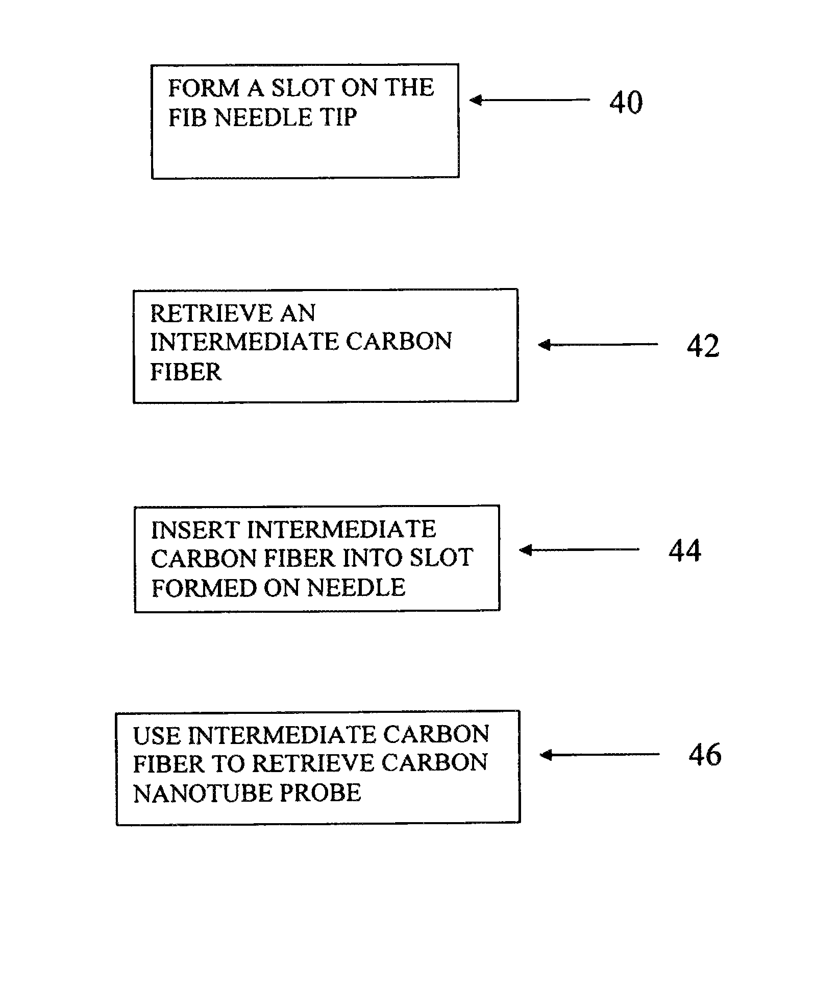
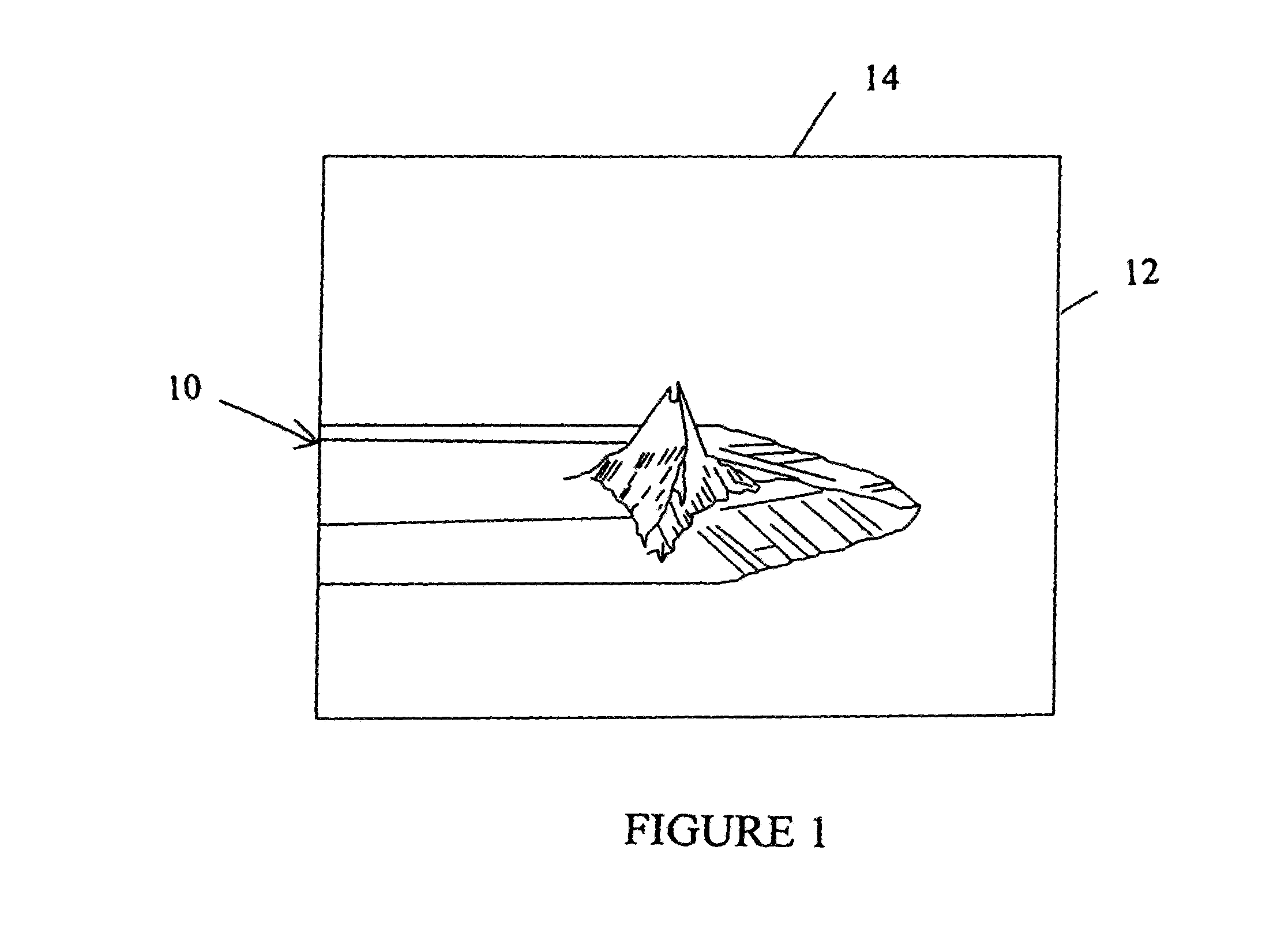
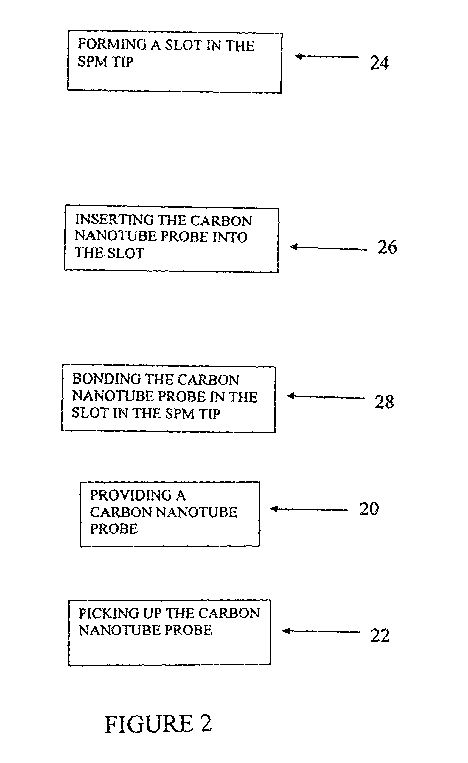
[0028]The method and system of the present invention produces a nanotube scanning tip as shown in FIG. 1. The nanotube scanning tip 10 comprises a carbon nanotube probe 14 attached perpendicular to the cantilever tip 12 axis. The system for attaching the carbon nanotube probe to the scanning probe includes a novel carbon fiber with a nanotube tip and a means for retrieving and picking up the carbon nanotube probe. An FIB tool is used to form a slot on a SPM tip, insert the carbon fiber with a nanotube tip into the slot on the SPM tip, and bond the carbon fiber with a nanotube tip in the slot on the SPM tip.

[0029]A method for attachin...


PUM

PropertyMeasurementUnit
tip diameteraaaaaaaaaa
diametersaaaaaaaaaa
sizeaaaaaaaaaa

Abstract

An easy and controllable method and system to attach a carbon nanotube to a scanning probe tip such as a scanning probe microscopy (SPM) tip using a focus ion beam (FIB) technique. The method and system includes selecting a carbon fiber by a Focus Ion Beam micromanipulator, picking up the carbon fiber with the nanotube tip, forming a slot on an SPM tip, and inserting the carbon fiber with the nanotube tip into the slot.

Description

[0001]This invention in a continuation-in-part of U.S. application Ser. No. 10 / 424,336 filed on Apr. 25, 2003, now U.S. Pat. No. 7,011,884 which is a divisional of U.S. application Ser. No. 09 / 528,259 filed on Mar. 17, 2000, now U.S. Pat. No. 6,582,673 and claims the benefit of priority to U.S. Provisional Application Ser. No. 60 / 511,787 filed Oct. 16, 2003.FIELD OF INVENTION[0002]This invention relates to nanotubes, in particular to methods and systems for attaching carbon nanotube probes to scanning probe microscopy (SPM) tips.BACKGROUND AND PRIOR ART[0003]Since the discovery of carbon nanotubes (CNT) in 1991, much has been done to characterize their properties and explore their potential applications. Currently, carbon nano particles including both nanotubes and monofilaments are found in extended commercial applications in modern technologies, for example, for manufacture of composite materials, nanoscale machines, flat panel displays, and computer memory devices. The wide appli...

Claims


Application Information

Patent Timeline
Patent Type & Authority Patents(United States)
IPC IPC(8): B23K11/22C23C8/00
CPCB82Y15/00B82Y30/00B82Y35/00B82Y40/00C01B31/0206G01Q70/12C01B32/15
Inventor CHOW, LEECHAI, GUANG-YU
Owner UNIV OF CENT FLORIDA RES FOUND INC
Learn More