Catalyst for purifying exhaust gas

a technology of catalyst and exhaust gas, which is applied in the direction of physical/chemical process catalyst, other chemical processes, separation processes, etc., can solve the problems of increasing the amount of noble metal, increasing the cost, and low purifying activity, and achieves good purifying activity, high density, and improved nox purifying performance after warming up

Inactive Publication Date: 2010-12-07
TOYOTA JIDOSHA KK
View PDF45 Cites 9 Cited by
  • Summary
  • Abstract
  • Description
  • Claims
  • Application Information

AI Technical Summary

Benefits of technology

[0017]Hereinafter, an exhaust-gas upstream side will be referred to as an “upstream side,” and an exhaust-gas downstream side will be referredtoas a “downstream side ” In accordance with the catalyst for purifying exhaust gas according to the present invention, a loading density of Rh is higher on a downstream side than on an upstream side. Rh is good in terms of the purifying activity of NOx in rich atmosphere that lacks oxygen. And, since HC and CO are oxidized on the upstream side so that oxygen is consumed, exhaust gases that flow into catalyst are likely to turn into rich atmosphere on the downstream side. Therefore, by loading Rh onto the downstream side with high density, the NOx purifying performance after warming up improves.
[0018]Moreover, loading Rh onto the downstream side with high density suffices, and it is allowable that the loading density of Rh on the upstream side can be low. Therefore, it is allowable that the loading amount of Rh can be equivalent to those having been done conventionally, and accordingly there is not any enlargement of costs, either.
[0019]Further, when Pt is loaded onto the upstream side with high density, the purifying performance of HC and CO in low-temperature region improves. And, even when Pt is loaded onto the downstream side with low density, there is hardly any influence on the purifying activities after warming up. Therefore, it is allowable that the loading amount of Pt can also be equivalent to those having been done conventionally, and accordingly the enlargement of costs can be suppressed.

Problems solved by technology

Accordingly, when the exhaust gases fall in low-temperature region in winter, at the time of start up, and the like, there has been such a drawback that the purifying activities are low.
However, when simply making the loading density of the noble metal higher, there is such a problem that the absolute amount of the noble metal increases so that the cost has risen.
However, even when making the loading density of the upstream-side noble metal higher, it hardly affects the purifying performance after the temperature of the catalyst rises up to the activation temperature of the noble metal (hereinafter, referred to as “after warming up”), and accordingly the noble metal has been wasted.
Moreover, there is even such a problem that the NOx purifying performance after warming up is not sufficient.

Method used


Image

  • Catalyst for purifying exhaust gas
  • Catalyst for purifying exhaust gas
  • Catalyst for purifying exhaust gas

Examples


examples

[0044]Hereinafter, the present invention will be explained in detail by means of examples and comparative examples.

example no.1

Example No. 1

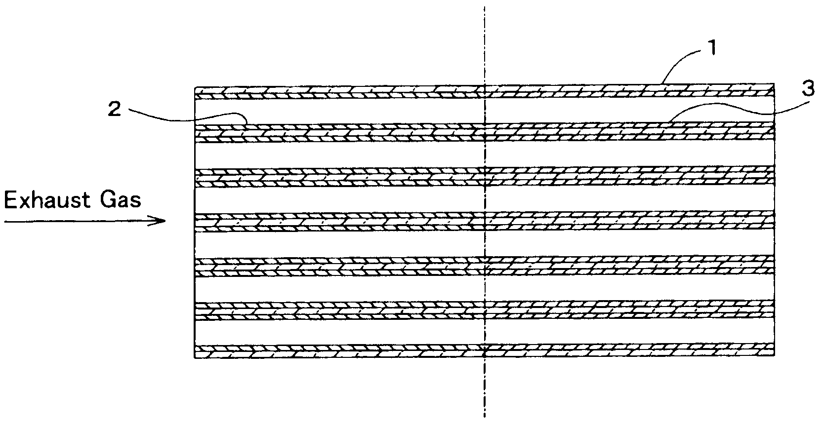
[0045]In FIG. 1, a schematic cross-sectional diagram of a catalyst for purifying exhaust gas according to a present example is illustrated. This catalyst for purifying exhaust gas comprises a honeycomb substrate 1 (length: 130 mm) being made of cordierite, upstream-side coating layers 2 being formed in a range of 65 mm from the upstream-side end surface of the honeycomb substrate 1, and downstream-side coating layers 3 being formed in a range of 65 mm from the downstream-side end surface of the honeycomb substrate 1. On the upstream-side coating layers 2 and downstream-side coating layers 3, Pt and Rh are loaded with different loading densities, respectively. Hereinafter, the manufacturing method of this catalyst for purifying exhaust gas will be explained, instead of the detailed explanation on the constructions.

[0046]A dinitrodiamine platinum solution with a predetermined concentration was used, was adsorption loaded onto a CeO2—ZrO2 solid-solution powder (CeO2:ZrO2=6...

example no.2

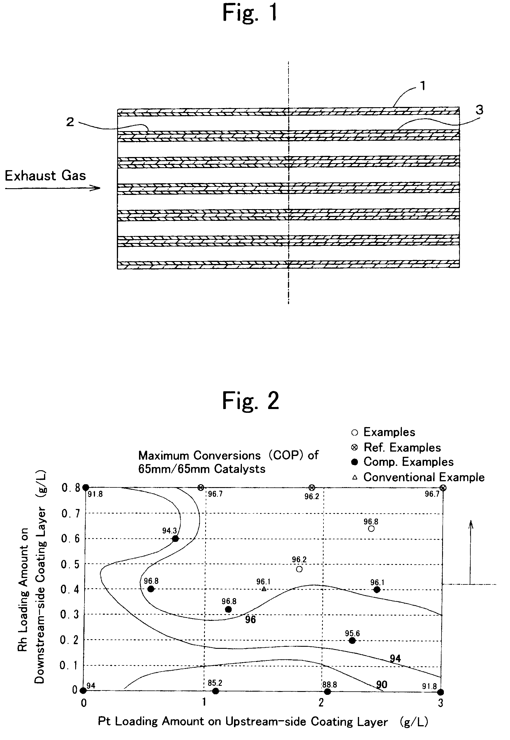
Example No. 2, Reference Example Nos. 1-3 & Comparative Example Nos. 1-10

[0054]Except that Pt or Rh was loaded respectively so that the loading amounts differed while using the same Ce02-Zr02 solid-solution powders as those in Example No. 1, catalytic powders were prepared in the same manner as Example No. 1. And, coating layers were formed similarly onto the same honeycomb substrate as that in Example No. 1, thereby preparing catalysts, whose loading amounts and loading distributions of Pt and Rh differed as indicated in Table 1, respectively. In all of them, on the entire catalyst, Pt came to be loaded in an amount of 1.5 g / L, and Rh came to be loaded in an amount of 0.4 g / L, respectively.

Conventional Example

[0055]Except that Pt or Rh was loaded respectively so that the loading amounts differed while using the same Ce02-Zr02 solid-solution powders as those in Example No. 1, a catalytic powder was prepared in the same manner as Example No. 1. And, coating layers were formed similar...


PUM

PropertyMeasurementUnit
lengthaaaaaaaaaa
lengthaaaaaaaaaa
thicknessaaaaaaaaaa

Abstract

In the present invention, it is an assignment to optimize a loading density of noble metal on catalyst.Pt is loaded in such an amount that a loading amount per 1 liter of a support substrate exceeds 0.75 g on an exhaust-gas upstream side of a coating layer, and a loading density of Rh in the coating layer is made so that it becomes higher on an exhaust-gas downstream side than on the exhaust-gas upstream side. The purifying performance after warming up improves by loading Rh with high density on the exhaust-gas downstream side that is likely to become rich atmosphere.

Description

CROSS-REFERENCE TO RELATED APPLICATIONS[0001]This application is a national phase application of International Application No. PCT / JP2007 / 064358, filed Jul. 20, 2007, and claims the priority of Japanese Application No. 2006-198471, filed Jul. 20, 2006, the contents of both of which are incorporated herein by reference.TECHNICAL FIELD[0002]The present invention relates to a catalyst for purifying exhaust gas, catalyst which can purify harmful components in exhaust gases from internal combustion engines, and the like, efficiently from low-temperature region to high-temperature region.BACKGROUND ART[0003]Conventionally, as a catalyst for purifying the exhaust gases of automobiles, three-way catalysts have been used, three-way catalysts which carry out the oxidation of CO and HC in the exhaust gases and the reduction of NOx therein simultaneously at the theoretical air-fuel ratio (stoichiometry), thereby purifying them. As for such a three-way catalyst, the following has been known wide...

Claims


Application Information

Patent Timeline
Patent Type & Authority Patents(United States)
IPC IPC(8): B01J23/00B01J21/00B01J20/00
CPCB01D53/945B01J23/42B01J23/464B01J23/63B01J35/0006B01J37/0248B01D53/9477B01D2255/1021B01D2255/1025Y02T10/22Y02T10/12B01D53/94F01N3/10
Inventor YAMATO, MASANORIKUNO, OJI
Owner TOYOTA JIDOSHA KK
Why Eureka
Try Eureka