
Method to reduce corner shunting during fabrication of CPP read heads

a technology of cpp read heads and corner shunting, which is applied in the field of magnetic read heads to achieve the effects of reducing the production of short circuits between hard bias/leads, increasing production yields, and easy removal

Inactive Publication Date: 2010-11-23
WESTERN DIGITAL TECH INC
View PDF11 Cites 4 Cited by
  • Summary
  • Abstract
  • Description
  • Claims
  • Application Information

AI Technical Summary

Benefits of technology

[0017]It is an advantage of the present invention that the production of short circuits between hard bias / leads is minimized, thus increasing production yields.
[0018]It is another advantage that photoresist is not encapsulated by hard bias / lead material and is thus more easily removed.
[0019]It is a further advantage of the present invention that more uniform topography is produced, thus simplifying subsequent processing steps.
[0020]It is another advantage of the present invention that corner shunting is reduced or eliminated.
[0021]It is yet another advantage of the present invention that a negative residual step height can be produced, allowing for easier CMP operations.

Problems solved by technology

A common problem with the fabrication of such small sensors is illustrated in FIGS. 5-15.

Method used


Image

  • Method to reduce corner shunting during fabrication of CPP read heads
  • Method to reduce corner shunting during fabrication of CPP read heads
  • Method to reduce corner shunting during fabrication of CPP read heads

Examples


Embodiment Construction

[0039]The preferred embodiment of the present invention is a method of fabrication of read sensors that utilizes fast-milling dielectric material that more closely matches the milling rate of sensor material. The present invention is also a disk drive including a magnetic head having a read head having milled sensor layers above the dielectric layer, and a method for producing this read head.

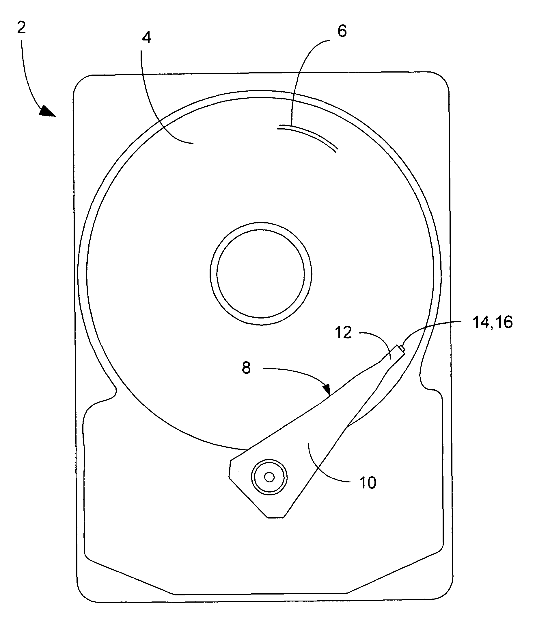
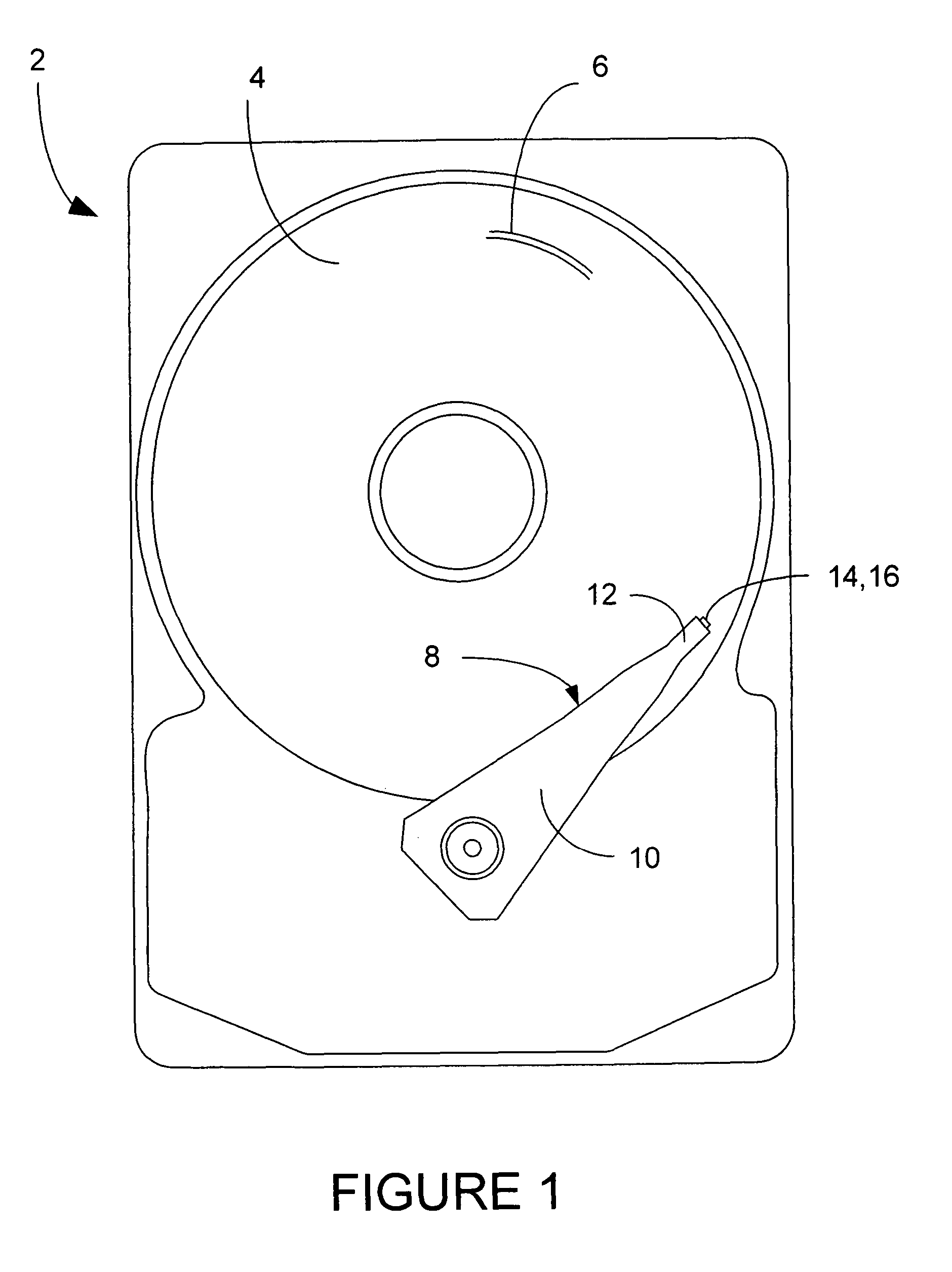
[0040]A hard disk drive 2 is shown generally in FIG. 1, having one or more magnetic data storage disks 4, with data tracks 6 which are written and read by a data read / write device 8. The data read / write device 8 includes an actuator arm 10, and a suspension 12 that supports one or more magnetic heads 14 included in one or more sliders 16.

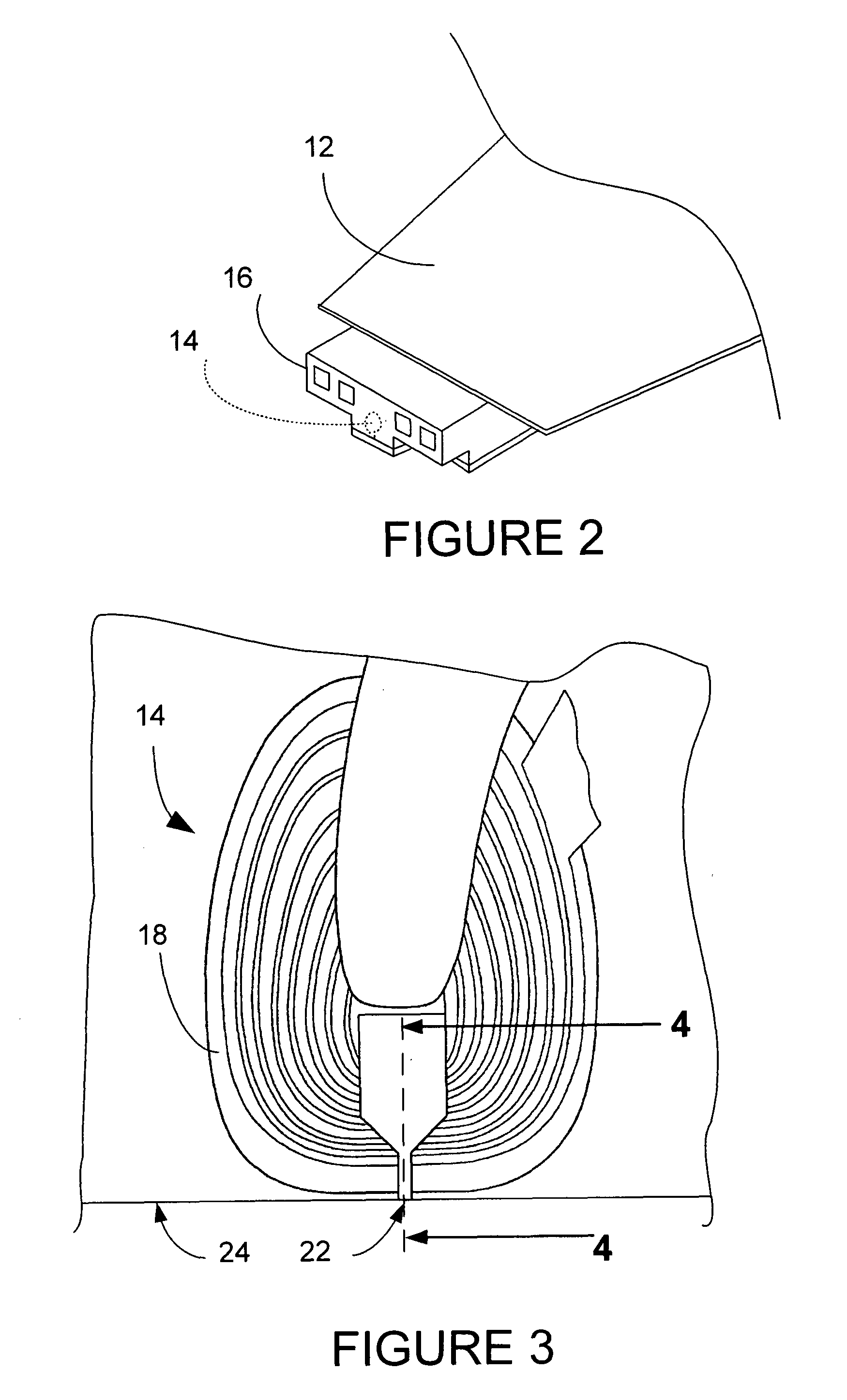
[0041]FIG. 2 shows a slider 16 in more detail being supported by suspension 12. The magnetic head 14 is shown in dashed lines, and in more detail in FIGS. 3 and 4. The magnetic head 14 includes a coil 18 and P1 pole, which also acts as S2 shield, thus making P1 / ...


PUM

PropertyMeasurementUnit
hard biasaaaaaaaaaa
compositionsaaaaaaaaaa
residual step heightaaaaaaaaaa

Abstract

A method is presented for fabricating a CPP read head having a CPP read head sensor and a hard bias layer which includes forming a strip of sensor material in a sensor material region, and depositing strips of fast-milling dielectric material in first and second fast-milling dielectric material regions adjacent to the sensor material region. A protective layer and a layer of masking material are deposited on the strip of sensor material and the strips of fast-milling dielectric material to provide masked areas and exposed areas. A shaping source, such as an ion milling source, is provided which shapes the exposed areas. Hard bias material is then deposited on the regions of sensor material and fast-milling dielectric material to form caps on each of these regions. The caps of hard bias material and the masking material are then removed from each of these regions.

Description

[0001]The following is a continuation in part of pending application Ser. No. 11 / 081,222, entitled “METHOD TO IMPROVE ABILITY TO PERFORM CMP-ASSISTED LIFTOFF FOR TRACKWIDTH DEFINITION,” filed Mar. 15, 2005 now U.S. Pat. No. 7,270,758, having at least one common inventor; and, claims priority from and incorporates by reference pending application Ser. No. 11 / 081,222.BACKGROUND OF THE INVENTION[0002]1. Field of the Invention[0003]The present invention relates generally to magnetic heads for reading data written to storage media, and more particularly to magnetic read heads for disk drives.[0004]2. Description of the Prior Art[0005]In recent years there has been a constant drive to increase the performance of hard disk drives by increasing the areal data storage density of the magnetic hard disk. This is done by reducing the written data track width, such that more tracks per inch can be written on the disk. This naturally requires that the width of the read head be reduced so magnetic...

Claims


Application Information

Patent Timeline
Patent Type & Authority Patents(United States)
IPC IPC(8): G11B5/127
CPCB82Y10/00B82Y25/00G11B5/3932Y10T428/1171G11B2005/3996G11B5/3163B05D5/12
Inventor FONTANA, JR., ROBERT E.HONG, YINGJAYASEKARA, WIPUL PEMSIRIZOLLA, HOWARD GORDON
Owner WESTERN DIGITAL TECH INC
Learn More