
Cooling apparatus

a technology of cooling apparatus and cooling water, which is applied in the direction of cooling apparatus, lighting and heating apparatus, defrosting, etc., can solve the problems of increasing the cost of the overall process, contaminating the overall process, and dissolved solids, etc., so as to improve the overall process heat transfer efficiency, reduce power consumption, and improve control

Active Publication Date: 2010-11-02
UNIVERSITY OF SURREY
View PDF9 Cites 12 Cited by
  • Summary
  • Abstract
  • Description
  • Claims
  • Application Information

AI Technical Summary

Benefits of technology

[0015]The selective nature of the membrane prevents undesirable solute(s) and other containments in the first solution from passing into the second solution.
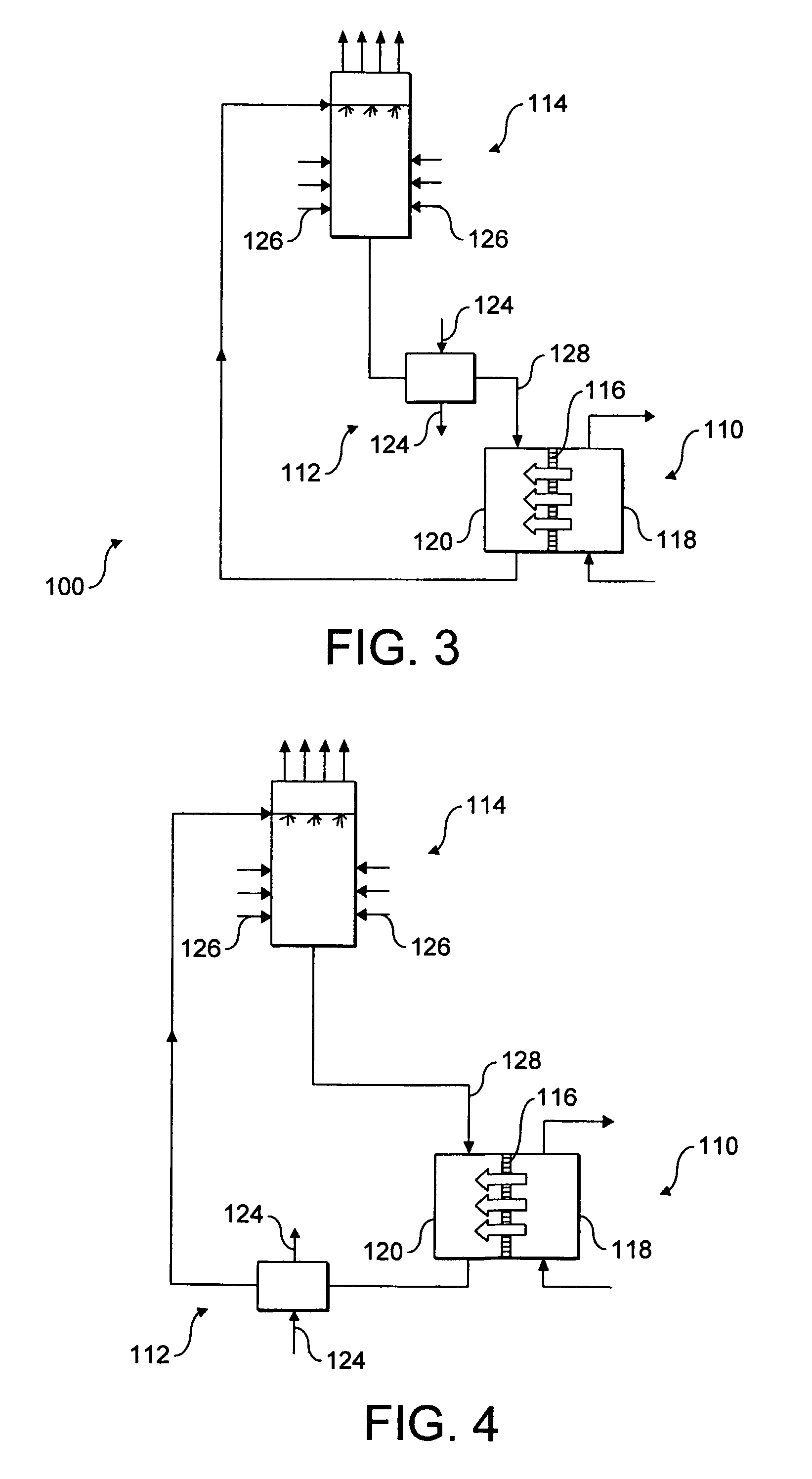
[0023]After solvent (e.g. water) from the first solution has passed into the second solution, the second solution may be at an elevated pressure (osmotic pressure when water is used as a solvent), even when a pressure is not applied to induce solvent flow from the first solution to the second solution. This is because the flow of solvent from the first solution into the second solution occurs along a concentration gradient. This pressure may be used to aid the transfer of the second solution to subsequent processing steps of the present invention. This pressure may be sufficient to transfer the second solution to subsequent processing steps, for example, without the aid of pumps. In one embodiment, excess pressure is converted into mechanical work. Thus, the pressure (e.g. osmotic pressure) generated in the second solution may be used to reduce the power consumption and / or increase the heat transfer efficiency of the overall process.
[0034]Cooling towers typically contain a porous filler material, known as decking (packing). The second solution is introduced into the top of the cooling tower and drips down through the decking, whilst a coolant, such as air, is blown through the decking, causing some of the solvent of the second solution to evaporate. The loss of heat by evaporation (evaporative cooling) lowers the temperature of the remaining second solution.
[0046]To improve the efficacy of the osmosis step, the first and / or second solution may be treated to reduce fouling and scaling of the membrane. Accordingly, anti-scaling and / or anti-fouling agents may be added to one or both solutions. Although not required, pressure may be applied to the first solution side of the membrane to increase the rate of flux of water across the membrane. For example, pressures of 1×10⁵ Pa to 5×10⁵ Pa [1 to 5 bar] may be applied, preferably pressures of 2×10⁵ Pa to 4×10⁵ Pa [2 to 4 bar]. Additionally or alternatively, the pressure on the second solution side of the membrane may be reduced. For example the pressure may be less than 1×10⁵ Pa [1 bar], preferably less than 0.5×10⁵ Pa [0.5 bar].

Problems solved by technology

As evaporation occurs, contaminants, such as dissolved solids, build up in the recirculating water.
Such contaminants can cause fouling, for example, as a result of biological growth, scale formation, corrosion and / or sludge deposition.
These additives tend to be expensive and have to be added continuously to the make-up water, adding to the cost of the overall process.
Heat from the air is transferred to the wet decking material, causing the water contained in the decking to evaporate.
As the water evaporates, contaminants in the water may deposit on the decking material.
Such deposits have a detrimental effect on the thermal efficiency and life of the air-cooler.

Method used


Image

  • Cooling apparatus
  • Cooling apparatus
  • Cooling apparatus

Examples


Embodiment Construction

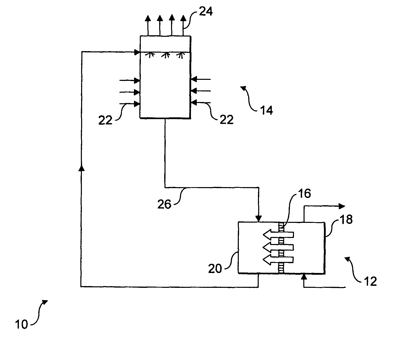
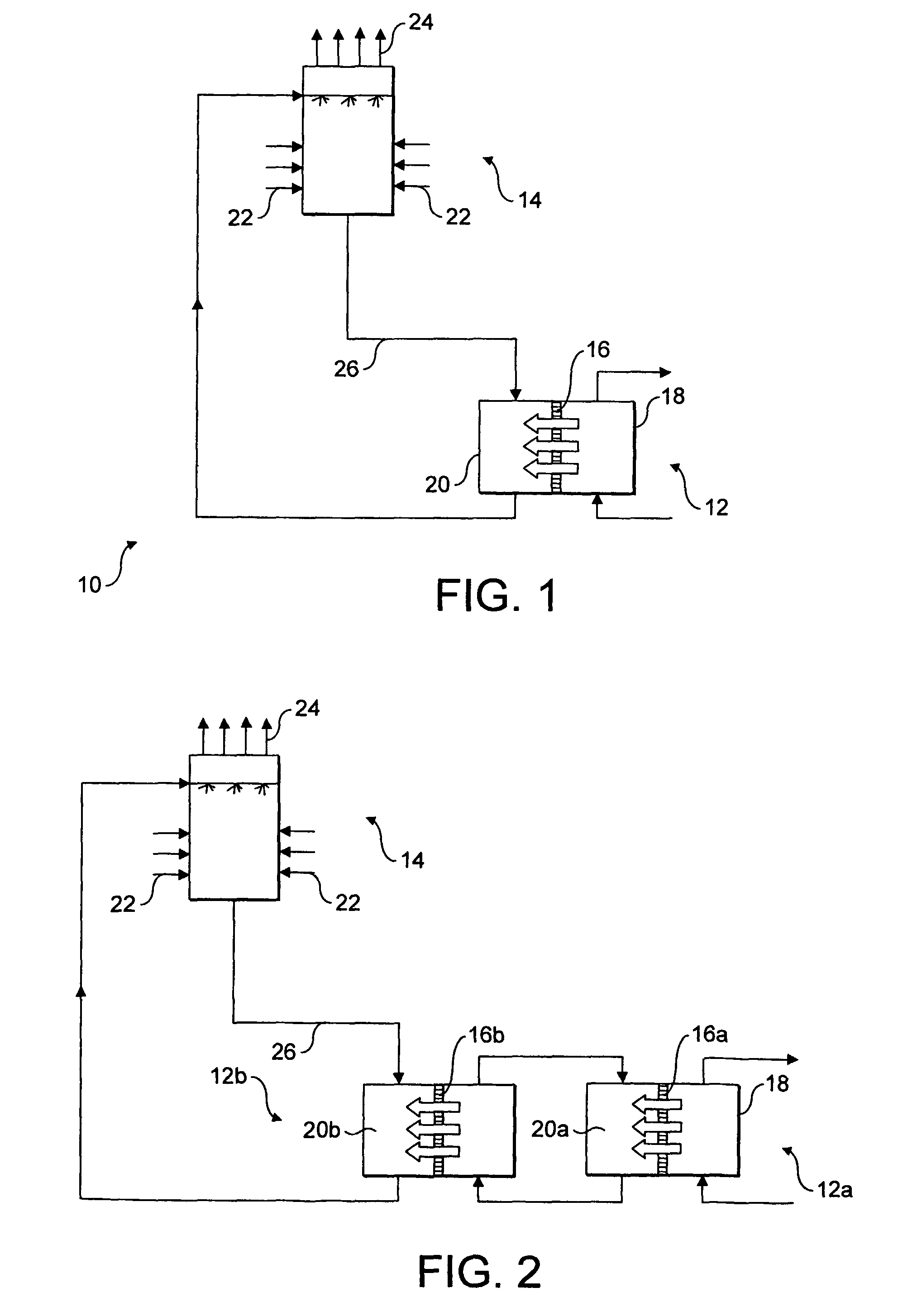
[0060]Referring to FIG. 1, there is provided an apparatus 10 for producing a cool stream of air.

[0061]The apparatus 10 comprises a housing 12 and an air cooler 14. The housing 12 comprises a selectively permeable membrane 16 for separating seawater 18 from a solution 20 formed by dissolving a known amount of sodium chloride in water.

[0062]In use, seawater 18 is circulated through the housing 12 on one side of the membrane 16, whilst sodium chloride solution 20 is circulated through the housing 12 on the opposite side of the membrane 16. The sodium chloride solution 20 in contact with the membrane 16 has a higher total dissolved salt (solute) concentration than the seawater 18. Thus, water flows from the seawater-side of the membrane 16 to the solution-side of the membrane 16 by osmosis.

[0063]The flow of water across the membrane 16 dilutes the sodium chloride solution 20. The diluted solution 20 is removed from the housing 12 and is introduced into the air cooler 14. The air cooler ...


PUM


Abstract

A process for introducing a solution into an evaporative cooling apparatus (14), said process comprising a) positioning a selectively permeable membrane (16) between a first solution (18) and a second solution (20) having a higher solute concentration than the first solution (18), such that the solvent from the first solution (18) flows across the selectively permeable membrane (16) to dilute the second solution (20), b) introducing the second solution into an evaporative cooling apparatus (14) in which solvent is removed from the second solution (20) by evaporation, and c) recycling the second solution (20) from step b) to step a) to draw solvent from the first solution (18).

Description

BACKGROUND OF THE INVENTION[0001]1. Field of the Invention[0002]The present invention relates to a method and apparatus for introducing a solution into a cooling apparatus. In particular, although not exclusively, the present invention relates to a method and apparatus for removing heat from a heat source.[0003]2. The Prior Art[0004]Heat exchangers are often used to remove excess heat from industrial processes. Typical heat exchangers include shell and tube-type heat exchangers, which comprise a length of tubing partially enclosed within a housing or shell. An industrial process stream containing excess heat is introduced into the tubing, whilst a coolant, such as water, is passed through the shell via a separate inlet and outlet. The water removes excess heat from the process stream. Thus, the water exiting the shell is at a higher temperature than the coolant entering the shell. The heated water stream is cooled in a cooling tower before it is recirculated back through the shell. ...

Claims


Application Information

Patent Timeline
IPC IPC(8): F25D17/02B01D61/00F28C1/00F28F25/00
CPCB01D61/002F28C1/00F28F25/00F28C2001/006Y02B30/70B01D61/0023
Inventor AL-MAYAHI, ABDULSALAMSHARIF, ADEL
Owner UNIVERSITY OF SURREY
Learn More