Eureka AIR delivers breakthrough ideas for toughest innovation challenges, trusted by R&D personnel around the world.

Detector for detecting a frequency-shift keying signal by digital processing

a digital processing and signal detector technology, applied in the direction of modulation, amplitude demodulation, pulse technique, etc., can solve the problems of receiver characteristics degradation, the modulated frequency cannot be arranged within the time length of one symbol, etc., and achieve the effect of preventing the degradation of receiver characteristics

Inactive Publication Date: 2010-09-28
LAPIS SEMICON CO LTD
View PDF14 Cites 0 Cited by
  • Summary
  • Abstract
  • Description
  • Claims
  • Application Information

AI Technical Summary

Benefits of technology

[0011]It is a primary object of the present invention to provide an FSK signal detector that is capable of preventing the receiver characteristics from being degraded even when the wavelength of a frequency modulated to a lower frequency side than the center frequency, for example, of an FSK signal is longer than the time length of one symbol.
[0023]According to the present invention, even when the wavelength of a frequency modulated to a lower frequency side than the center frequency, for example, of an FSK signal is longer than the time length of one symbol, the degradation of receiver characteristics can be prevented. For example, even under the condition of (center frequency of IF)<(frequency equivalent to the modulating speed)×1.25 (for minimum-shift keying), FSK signals can be satisfactorily detected.

Problems solved by technology

For that reason, in correlation filters, there is a problem that the wavelength of a modulated frequency cannot be arranged within the time length of one symbol.
On the other hand, if the correlation coefficient sequences of correlation filters are made longer to obtain a correlation at a period of time longer than one symbol period, then the problem of the degradation of receiver characteristics will arise.

Method used


Image

  • Detector for detecting a frequency-shift keying signal by digital processing
  • Detector for detecting a frequency-shift keying signal by digital processing
  • Detector for detecting a frequency-shift keying signal by digital processing

Examples


Embodiment Construction

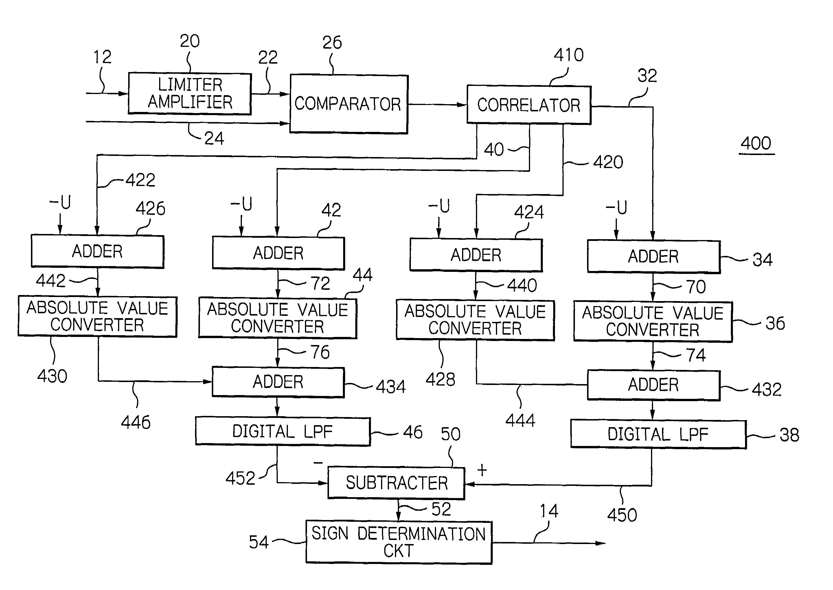
[0034]An embodiment of a frequency-shift keying (FSK) signal detector according to the present invention will hereinafter be described in detail with reference to the accompanying drawings. Referring to FIG. 1, the FSK signal detector of this embodiment, generally designated with a reference numeral 10, is configured to frequency-detect an FSK signal 12 by digital processing and output demodulated data 14, and includes a limiter amplifier 20 to which the FSK signal 12 is input, and a comparator 26 to which the output 22 of the limiter amplifier 20 and an input 24 are connected.

[0035]The comparator 26 has its output 28 connected to a correlator 30. The correlator 30 has its one output 32 connected to a first adder 34 for subtracting a predetermined value. The adder 34 has its output 70 connected to a first absolute value converter 36, which has its output 74 connected to a first digital low-pass filter (LPF) 38. The first adder 34, first absolute value converter 36, and first digital...


PUM


Abstract

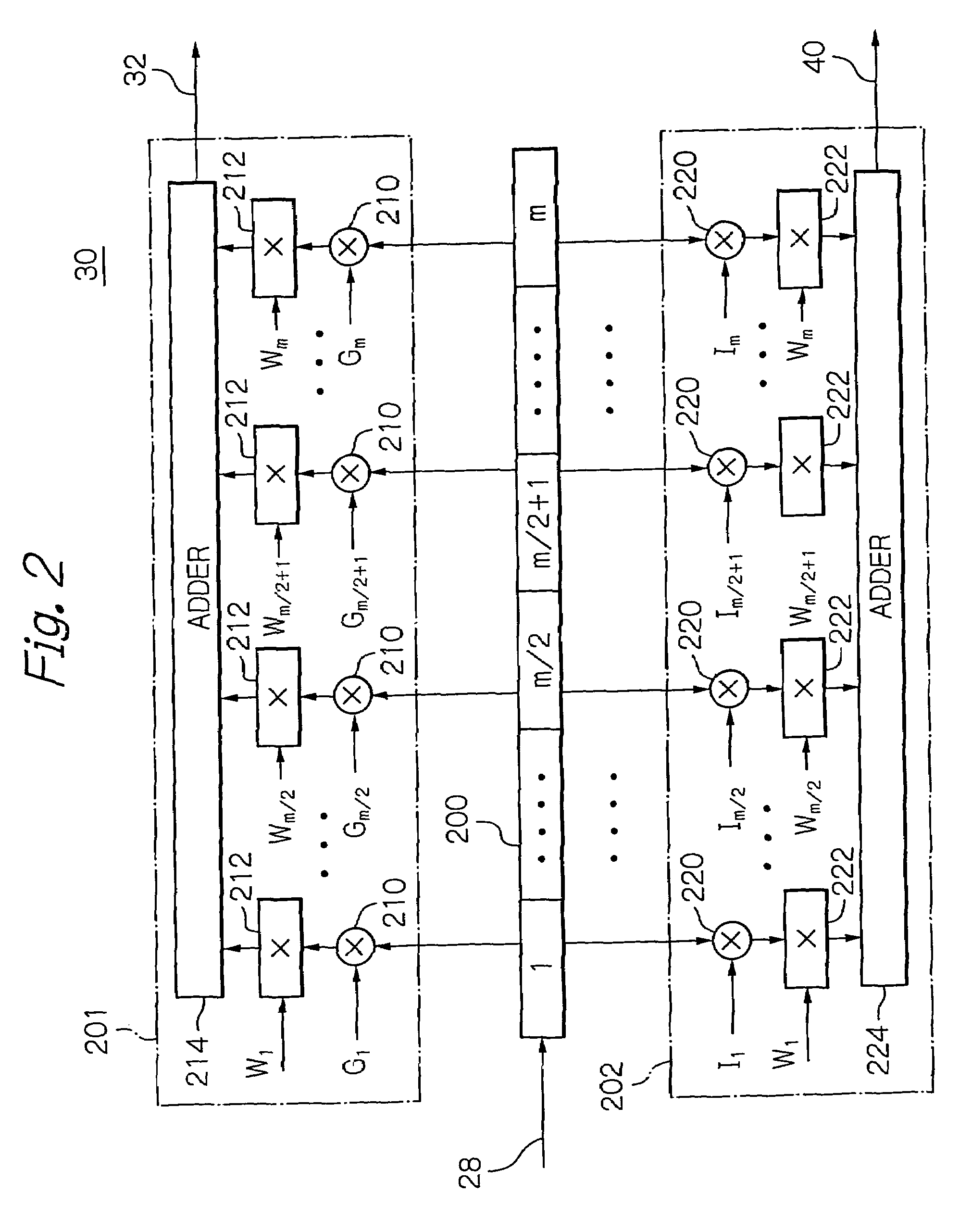
A frequency-shift keying (FSK) signal detector includes a binarizing circuit for receiving an FSK signal and expressing amplitude of the FSK signal in binary; a correlator for receiving the FSK signal expressed in binary and acquiring a correlation of the FSK signal; and an arithmetic unit for performing an arithmetic operation on the output of the correlator to detect and output the FSK signal. The correlator includes plural stages of shift register for sequentially shifting the FSK signal in response to a clock signal; a correlation filter for obtaining the correlation by a correlation signal sequence and a window function signal sequence which obtain a correlation value at one of two frequency components generated by frequency-shift keying; and another correlation filter for obtaining the correlation by a correlation signal sequence and a window function signal sequence which obtain a correlation value at the other of the two frequency components.

Description

BACKGROUND OF THE INVENTION[0001]1. Field of the Invention[0002]The present invention relates to a frequency-shift keying (FSK) signal detector for detecting an FSK signal, and more particularly to such a detector for detecting an FSK signal by digital processing.[0003]2. Description of the Background Art[0004]As a conventional FSK signal detector that detects an FSK signal by digital processing, for example, there is one which converts the output of an analog receiver to binary information, then detects frequency components by digital signal processing, and carries out demodulation. The conventional FSK frequency detector receives an input signal converted to an intermediate frequency (IF) and makes demodulation possible. In the case where the center frequency of the input IF signal to the FSK frequency detector preserves the following relationship, this conventional demodulation is possible.[0005]Center frequency f0 of IF≧(Frequency fd equivalent to the modulating speed)×1.25 (for...

Claims


Application Information

Patent Timeline
Patent Type & Authority Patents(United States)
IPC IPC(8): H03C1/52H03K9/00H04L7/00H04L27/00H04B3/20
CPCH04L27/1563
Inventor AKAHORI, HIROJI
Owner LAPIS SEMICON CO LTD
Why Eureka
Eureka Blog
Learn More